• To anyone looking to acquire commercial radio programming software:

    Please do not make requests for copies of radio programming software which is sold (or was sold) by the manufacturer for any monetary value. All requests will be deleted and a forum infraction issued. Making a request such as this is attempting to engage in software piracy and this forum cannot be involved or associated with this activity. The same goes for any private transaction via Private Message. Even if you attempt to engage in this activity in PM's we will still enforce the forum rules. Your PM's are not private and the administration has the right to read them if there's a hint to criminal activity.

    If you are having trouble legally obtaining software please state so. We do not want any hurt feelings when your vague post is mistaken for a free request. It is YOUR responsibility to properly word your request.

    To obtain Motorola software see the Sticky in the Motorola forum.

    The various other vendors often permit their dealers to sell the software online (i.e., Kenwood). Please use Google or some other search engine to find a dealer that sells the software. Typically each series or individual radio requires its own software package. Often the Kenwood software is less than $100 so don't be a cheapskate; just purchase it.

    For M/A Com/Harris/GE, etc: there are two software packages that program all current and past radios. One package is for conventional programming and the other for trunked programming. The trunked package is in upwards of $2,500. The conventional package is more reasonable though is still several hundred dollars. The benefit is you do not need multiple versions for each radio (unlike Motorola).

    This is a large and very visible forum. We cannot jeopardize the ability to provide the RadioReference services by allowing this activity to occur. Please respect this.

CB radio installation in a 1998 Volvo wagon

Status
Not open for further replies.

mmckenna

I ♥ Ø
Joined
Jul 27, 2005
Messages
25,516
Location
United States
Those are all 800MHz antennas.
Left to right:
Larsen NMOSPEC-800 5.4dBi
Motorola branded 800
1/4 wave 800.

The Larsen is going to get you the most metal in the air, but as Jon said, it's going to be a very poor performer.
But, you've got something to try. See if it works well enough to do what you want.
 
Joined
Feb 12, 2017
Messages
50
Those are all 800MHz antennas.
Left to right:
Larsen NMOSPEC-800 5.4dBi
Motorola branded 800
1/4 wave 800.

The Larsen is going to get you the most metal in the air, but as Jon said, it's going to be a very poor performer.
But, you've got something to try. See if it works well enough to do what you want.

Thanks for the information. Could any of these antennas be modified for CB use? Or could I build an antenna with the parts from these?
 

mmckenna

I ♥ Ø
Joined
Jul 27, 2005
Messages
25,516
Location
United States
Thanks for the information. Could any of these antennas be modified for CB use? Or could I build an antenna with the parts from these?

None of them can really be modified for CB unless you found a 108 inch long whip that would fit in place of one of the whips, but that isn't going to happen.

NMO27 really is your best bet.
 
Joined
Feb 12, 2017
Messages
50
Question about grounding; I am going to use a 2 wire trailer harness disconnect in this installation. That will involve cutting the factory wire from the CB body leaving about a foot, then connecting the two wire disconnect piece. My plan then was to run the ground wire immediate to the chassis, while running the power wire through the firewall and to the positive battery terminal. I figured I would splice the in line fuse somewhere up near the battery, but somewhere I could tuck it out of the way from moving parts. I plan to use quality crimp connectors for all the splices and will also use heat shrink tape around any splices.

Do you think grounding after the quick connect piece is a bad idea? We're only talking about 12"-18" from the radio chassis to ground. The power wire will be 5-6'.
 

Rred

Member
Joined
Nov 21, 2014
Messages
830
Grounding to the chassis "at" the radio can work, if you have a solid electrical ground from that point to the common ground point for the battery. Instead of measuring or gambling it can be simpler to just run both wires to the battery. You could check the quality of that ground point with an ohmmeter, voltmeter, your choice, with long enough leads. (Easier to run the wire.(G)

There are also split thoughts about fuses. Some radio manufacturers want fuses in both power lines, located right up by the battery. This is partly to prevent a problem if one of your lines is not at a perfect 0/12 volts and you get a voltage fault (loop) in the unfused one. Others say this is not a real-world concern. See what your car and radio makers each say, pick what suits you best.

A quality wiring job (no twist-and-tape) with good chafe protection probably counts more than everything else.
 

RFI-EMI-GUY

Member
Joined
Dec 22, 2013
Messages
7,503
Ground at the chassis as close to the radio as possible . Grounding at the battery terminal isn't recommended because of potential chassis ground lead fault conveying starter current into the radio and the coax. Could set fire to the interior and headliner.

Sent from my SM-T350 using Tapatalk
 

mmckenna

I ♥ Ø
Joined
Jul 27, 2005
Messages
25,516
Location
United States
Short ground connections are a good way to bleed off noise. Power wires can act like antennas.
Ground the radio with as short a wire as possible. If you still feel the need to run to the battery, that's up to you.
 
Joined
Feb 12, 2017
Messages
50
Short ground connections are a good way to bleed off noise. Power wires can act like antennas.
Ground the radio with as short a wire as possible. If you still feel the need to run to the battery, that's up to you.

Ok, so I do want to ground it as quickly as possible and I believe I have a suitable ground not that far away from the radio. That said, will I severely compromise my ground if it is grounded AFTER the quick disconnect pictured below? Or does the ground have to run straight from the radio to the grounding point?
 

Attachments

  • IMG_0610.jpg
    IMG_0610.jpg
    21.6 KB · Views: 133

RFI-EMI-GUY

Member
Joined
Dec 22, 2013
Messages
7,503
When you use those quick disconnects, be sure the positive wire from battery is the female protected side. I have seen those spliced the wrong way.

Sent from my SM-T350 using Tapatalk
 
Joined
Feb 12, 2017
Messages
50
When you use those quick disconnects, be sure the positive wire from battery is the female protected side. I have seen those spliced the wrong way.

Sent from my SM-T350 using Tapatalk

I didn't realize there was a "side" to this; I assume red would be the side to wire to the battery?
 

RFI-EMI-GUY

Member
Joined
Dec 22, 2013
Messages
7,503
I didn't realize there was a "side" to this; I assume red would be the side to wire to the battery?

When you pull the connectors apart, there will be an exposed terminal on one red side. You want that wire going to the radio not the battery.
 

Project25_MASTR

Millennial Graying OBT Guy
Joined
Jun 16, 2013
Messages
4,384
Location
Texas
Grounding to the chassis "at" the radio can work, if you have a solid electrical ground from that point to the common ground point for the battery. Instead of measuring or gambling it can be simpler to just run both wires to the battery. You could check the quality of that ground point with an ohmmeter, voltmeter, your choice, with long enough leads. (Easier to run the wire.(G)


There are also split thoughts about fuses. Some radio manufacturers want fuses in both power lines, located right up by the battery. This is partly to prevent a problem if one of your lines is not at a perfect 0/12 volts and you get a voltage fault (loop) in the unfused one. Others say this is not a real-world concern. See what your car and radio makers each say, pick what suits you best.


A quality wiring job (no twist-and-tape) with good chafe protection probably counts more than everything else.


98% of all vehicles on the road in North America are Negative chassis ground. A little electrical common sense explains the reasoning of manufacturers.

If you have a DC grounded antenna, then a properly install antenna mount will be grounded to the chassis. If you take both leads to the battery, you have created a potential ground loop. If you lose the chassis grounding between the negative post and chassis, current from all other loads will now flow down the antenna coax through the radio and to the battery. This is why the negative fuse becomes important.

Of course, grounding to chassis with the radio eliminates the potential difference without requiring extra hardware…that's why it is the traditional method of powering radios through the American manufacturers.


Sent from my iPhone using Tapatalk
 
Joined
Feb 12, 2017
Messages
50
Thanks everyone for their responses above and on this thread in general.

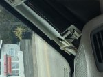
I'm getting ready to run the antenna wire down the door pillar and I have two questions before I do that. First, please see the attached picture. There is a wire that powers the sun visor mirror light, the plugged connector for which is visible in the photo. Since I really don't need to have a light up mirror in my passenger seat, should I disconnect that plug? The coax is going to run right along side of it and pass through the dashboard at the exact point where that plug is. I want to do everything I can to eliminate noise from the cars electronics. Second, I have about 2 1/2" feet of coiled coax left in this wire, based on what was said higher up in the thread, I plan to loop it into 2 or three 6" diameter loops, zip tie it, and leave that material in the headliner. Would it be a good idea to leave these zip tied loops right under the NMO mount or should it be off to the side? Thanks.
 

Attachments

  • IMG_0621.jpg
    IMG_0621.jpg
    60.3 KB · Views: 115

RFI-EMI-GUY

Member
Joined
Dec 22, 2013
Messages
7,503
No need to disconnect that mirror lamp plug. It is probably not a noise generator and the coax shield is there to protect from that. I would be hesitant to leave hoops of coax in the headliner as it will weigh it down possibly to droop, and because it may create an annoying rattle. Leave just enough service loop in case you need to loosen the NMO base in the future.

Sent from my SM-T350 using Tapatalk
 

mmckenna

I ♥ Ø
Joined
Jul 27, 2005
Messages
25,516
Location
United States
2 1/2 feet isn't much.

I agree with RFI-EMI-GUY, leave some slack under the NMO mount just in case you ever need to remove it. Not much, but a few inches. I've never needed to remove an NMO mount, but there is also no point in pulling the cable tight. A bit of slack isn't going to hurt anything.
For the slack, it would do better under the dash near the radio. More than likely any issues you have with the coax will be at the termination where it connects to the radio. Leaving some slack so you can get the connector out from under the dash for repair or re-termination is a good idea.
 
Joined
Feb 12, 2017
Messages
50
Ok so I just got my Larsen NMO27 in the mail. All the rest of the set up is complete. All I need to do now is drill the roof hole and run all the cables. I have a quick questions about the hole drilling and so forth;

After I drill the hole, should I shoot a little primer on the expose metal of the roof? I'm concerned about rust, but I also don't want to do anything that would hurt the antennas functionality. Also, I asked further upthread where I should put the small coil of slack that I will have in the antenna cable. About 2 1/2" zip ties into a 6" coil per a suggestion from others. Should that go right under the NMO base or off to the side. I'm not concerned about weight as my headliner is very strong and there is a support buttress molded into the headliner itself right near the installation point. Thanks for all your help this far. Will post pics of completed install soon.
 

RFI-EMI-GUY

Member
Joined
Dec 22, 2013
Messages
7,503
If you used the special NMO hole saw there should be a band of exposed metal for the antenna base to ground to. You want an electrical connection at the base, so exposed metal is good. I would use some dielectric grease from an Auto parts store to provide water proofing of the O ring and protection from rust.

After installing the base, use an ohmmeter to verify continuity between the outer shield of the coax and the vehicle body. You should have zero ohms.

Sent from my SM-T350 using Tapatalk
 
Joined
Feb 12, 2017
Messages
50
I'm not going to use one of those special drills, just a brand new Irwin 3/4" bimetallic hole saw. I will have an assistant inside the car holding up a backer board with the headliner removed. I've tested the hole saw and it cuts an accurate and a very nice hole. So, I know there will be a portion of the sheet metal (the inner rim of the hole) that will def. be exposed metal; what other metal should be exposed or what other metal is exposed using one of those special NMO holesaws?
 

RFI-EMI-GUY

Member
Joined
Dec 22, 2013
Messages
7,503
The NMO saw cuts a thin strip of exterior paint, just enough to mate with the brass threaded portion of the NMO base that is just inside the O ring. You can sand and expose this small ring. Then put dielectric grease on the exposed metal and o ring before tightening down.

Sent from my SM-T350 using Tapatalk
 
Status
Not open for further replies.
Top