Good morning!
I had an eventful weekend wrestling with my new HF rig, along with a a new LDG Z-11 Pro II ATU and setting up an inverted V antenna. I'm here seeking advice from pros who might lend their expertise to my current dilemma.
Equipment:
The Situation:
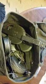
On Friday evening, I hoisted my first inverted V antenna and connected the rig expert, only to find an SWR of 7.5 @ 28.5 MHz Despite various attempts to adjust by expanding and shortening the ends of the military antenna (I did this by winding it up on the attached insulator spools), I could only marginally affect the SWR, with minimal improvement (+/- 1.00).
Further inspection revealed that SWR on all the other bands ranged from 5 to 8, with the one outlier with SWR of 1.58) oddly at 450 MHz. With time running short, I decided to test whether the LDG could tune up the antenna as is. I positioned everything on a table at about 40' from the antenna feed point, lowered the power on the IC-7000 to 10 watts on AM, and attempted to tune in the 10-meter band, but to no avail. Even after increasing power to 30 watts, the LDG failed to find a match. I then also tried on the 11m and 6m bands with the same result.
As far as reception goes, I scanned for signals for about 5 minutes and I couldn't get anything, though I recognize that this alone isn't conclusive evidence of an issue.
Best Guesses:
Is the antenna setup flawed, or could the LDG just be malfunctioning? I anticipated the LDG should be capable of tuning an SWR of less than 9 or 10 to an acceptable match. I'm considering trimming down the legs of the inverted V, as I primarily intend to use the antenna for 11m/10m and 6m, which should ideally bring down the SWR. However, I'm unsure if I have a defective ATU, the SWR is beyond its capabilities to tune, or if I just have an atrocious antenna/setup and need to start from scratch.
Any insights or suggestions would be greatly appreciated!
I had an eventful weekend wrestling with my new HF rig, along with a a new LDG Z-11 Pro II ATU and setting up an inverted V antenna. I'm here seeking advice from pros who might lend their expertise to my current dilemma.
Equipment:
- IC-7000
- LDG Z-11 Pro II ATU
- RigExpert AA-650 ZOOM
- 40' RG8 cable to ATU/radio
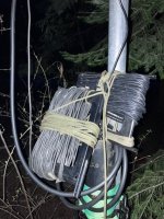
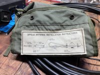
- Military surplus 200' Center-fed Dipole Antenna at a height of 34 feet, on a steel pole
- Antenna Location: Situated amidst a forest of towering evergreen trees, with the antenna positioned between a metal-roofed shop and a similarly roofed home (approximately 30' from both). I ran the legs of the inverted V away from the structures, with the ends of the antenna tied to trees about 8 feet in the air.
The Situation:
On Friday evening, I hoisted my first inverted V antenna and connected the rig expert, only to find an SWR of 7.5 @ 28.5 MHz Despite various attempts to adjust by expanding and shortening the ends of the military antenna (I did this by winding it up on the attached insulator spools), I could only marginally affect the SWR, with minimal improvement (+/- 1.00).
Further inspection revealed that SWR on all the other bands ranged from 5 to 8, with the one outlier with SWR of 1.58) oddly at 450 MHz. With time running short, I decided to test whether the LDG could tune up the antenna as is. I positioned everything on a table at about 40' from the antenna feed point, lowered the power on the IC-7000 to 10 watts on AM, and attempted to tune in the 10-meter band, but to no avail. Even after increasing power to 30 watts, the LDG failed to find a match. I then also tried on the 11m and 6m bands with the same result.
As far as reception goes, I scanned for signals for about 5 minutes and I couldn't get anything, though I recognize that this alone isn't conclusive evidence of an issue.
Best Guesses:
Is the antenna setup flawed, or could the LDG just be malfunctioning? I anticipated the LDG should be capable of tuning an SWR of less than 9 or 10 to an acceptable match. I'm considering trimming down the legs of the inverted V, as I primarily intend to use the antenna for 11m/10m and 6m, which should ideally bring down the SWR. However, I'm unsure if I have a defective ATU, the SWR is beyond its capabilities to tune, or if I just have an atrocious antenna/setup and need to start from scratch.
Any insights or suggestions would be greatly appreciated!


