• To anyone looking to acquire commercial radio programming software:

    Please do not make requests for copies of radio programming software which is sold (or was sold) by the manufacturer for any monetary value. All requests will be deleted and a forum infraction issued. Making a request such as this is attempting to engage in software piracy and this forum cannot be involved or associated with this activity. The same goes for any private transaction via Private Message. Even if you attempt to engage in this activity in PM's we will still enforce the forum rules. Your PM's are not private and the administration has the right to read them if there's a hint to criminal activity.

    If you are having trouble legally obtaining software please state so. We do not want any hurt feelings when your vague post is mistaken for a free request. It is YOUR responsibility to properly word your request.

    To obtain Motorola software see the Sticky in the Motorola forum.

    The various other vendors often permit their dealers to sell the software online (i.e., Kenwood). Please use Google or some other search engine to find a dealer that sells the software. Typically each series or individual radio requires its own software package. Often the Kenwood software is less than $100 so don't be a cheapskate; just purchase it.

    For M/A Com/Harris/GE, etc: there are two software packages that program all current and past radios. One package is for conventional programming and the other for trunked programming. The trunked package is in upwards of $2,500. The conventional package is more reasonable though is still several hundred dollars. The benefit is you do not need multiple versions for each radio (unlike Motorola).

    This is a large and very visible forum. We cannot jeopardize the ability to provide the RadioReference services by allowing this activity to occur. Please respect this.

Cobra 139XLR base station modification identification

OldCobraCB

Newbie
Joined
Jun 27, 2025
Messages
4
Hi everyone, I am new to radios and need some help.

I recently purchased online an old Cobra 139XLR base station and upon receiving it have found that it has had some modifications.

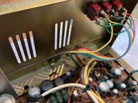
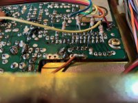
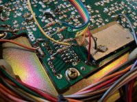
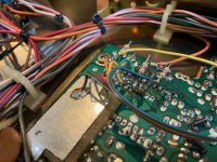
Somebody installed three switches in the back of the radio which are wired (some with 5% variance 4700 ohm resistors) to the back of the chip (which is the stock Uniden D858), as well as some other components around the chip. Does anyone know what this modification is?

The switches are in the corner by the external speaker outlets...
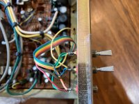
IMG_0414.jpg
IMG_0421.jpg

The wires are routed across the underside of the board...
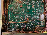
IMG_0416.jpg

And to the underside of the chip, along with the 4700 ohm resistors...
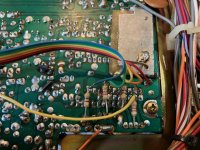
IMG_0418.jpg
IMG_0417.jpg
IMG_0419.jpg
IMG_0420.jpg

There is also a little thingy-ma-jig near the speaker which seems a little out of place. I found it wrapped in electrical tape. Advise as to what it is?
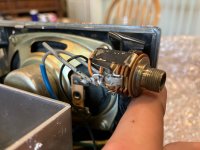
IMG_0415.jpg

Any help would be appreciated. Thanks in advance!
 

WSAC829

Mike Oscar 225
Premium Subscriber
Joined
Jan 13, 2024
Messages
342
Location
EN64ak
This is just my semi educated guess but more than likely the 3 switches are for extra channels (above 40 and below 1) and 1 of those switches might possibly be for the 10k Alpha channels. The taped up part looks to be the original external speaker socket. They probably removed it to use its hole in the case for 1 of the switches. You’ll probably need to buy or find somebody with an external in-line or wireless frequency counter to know where flipping those switches takes you to channel-wise. Otherwise you’ll be flying blind not knowing what frequency you are on which can get very frustrating. Otherwise it looks like they did a pretty nice job on the modification..
 

OldCobraCB

Newbie
Joined
Jun 27, 2025
Messages
4
Here's something I forgot that I see now is a little important; there was a small note taped to the top of the radio showing how to position the switches. The switches are numbered 1-2-3 with the broken one being 1. the note reads exactly as follows:

26865
1 2 3
up down up
reg ch
up mid mid​

So it's probably safe to say has extra channels.

Just a thought; could I possibly revert it to the original frequency range and number of channels by simply removing the switches and everything associated with them?
 

N1EXA

FT8 Huntin Mudd Duck on the deep end of the pond !
Joined
Mar 3, 2022
Messages
324
Location
Acushnet Heights New Bedford MA - GRID FN41 mp
Hello- Pretty common Modification which I did on my Cobra 148 to go into free band and the edge of 10 meters.
You can google it and find a wide field of web pages covering this topic.
Seeing the Guy or Gal who did this did not tape a chart to the top or label anything your going blind into what switches
override the processor programming.
If you have a frequency counter tapped off the processor test point or key up to a dummy load and transmitt you can get an idea
what going on.
I would not start chopping wires until you feel confidant you know whats going on.

Start off first with all the switches off and see if its on the normal CH Band.
These switches are overiding the programming so nothing will be in any order that makes it easy.


Pete N1EXA
 
Last edited:

kc2asb

Member
Joined
Dec 31, 2015
Messages
1,171
Location
NYC Area
+3 Those switches are definitely for the "extra channels" modification. I once owned a Cobra 142GTL that had been modified in the exact same way, except the switches were placed on the side of the cabinet for easier access. The previous owner also included a chart showing the switch positions and channel layout above Ch. 40 and below Ch. 1.

I believe the 139XLR and the 142GTL are essentially the same radio.
 

N1EXA

FT8 Huntin Mudd Duck on the deep end of the pond !
Joined
Mar 3, 2022
Messages
324
Location
Acushnet Heights New Bedford MA - GRID FN41 mp
This may get you head into whats going on


These switches are Grounding the pins to change the Processor programming the resistors are tied to 5 volts so when then
the switch is not on it forces the wire to a TTL Hi status instead of floating with no voltage.

This is TTL Logic commands so the want to see ground or 5 Volts ( 1 or 0 ) if you leave the wire floating the circiut
will not know where to go.

Pete N1EXA
 

tramd

Member
Joined
Jul 26, 2021
Messages
27
The 138XLR and 139XLR have the 858 PLL in it, so it is from 1977 or 1978. 1977 was the first year of the 40 channel radios. In 1979 the 8719 PLL was used, and the radio became the 142GTL. The 858 PLL was capable of 399 channels with four DPDT switches and some diodes across the terminals of the switches. With three DPDT switches and some diodes, they have about 199. The FCC wasn't too happy about that and stopped Uniden from using the 858PLL, so they used the 8719 in most of their boards after that. Usually, channels 16-35 will be used to get the lower and upper channels. Only a frequency counter will tell you what channels to use and what frequencies you're on, as there are many ways and types of switches to do this mod.
 

OldCobraCB

Newbie
Joined
Jun 27, 2025
Messages
4
What about with three SPDT switches? No DPDT switches here.

Also, what are CC1 and CC2? That's where the resistors bridge to from the PLL.
 
Last edited:

tramd

Member
Joined
Jul 26, 2021
Messages
27
CC1and CC2 are coming from the channel selector switch. By cutting the traces to the 858PLL and adding switches, the switches take control of the PLL instead of the channel selector and allow the radio to go where no radio has gone before. Like I said, there were many ways to use different types of switches to get the extra frequencies. Some used the NB and ANL switches on the radio. Some used 6 position rotary switches and different combinations of SPDT, SPST, DPDT and DPST. There were also external boxes with switches so as not to drill holes in the radio. There were also external thumb wheel switch boxes. Also after market items like the Expo kits and today the DigiMax Lite with its rotary encoder and digital readout and other digital types using rotary encoders.
 

OldCobraCB

Newbie
Joined
Jun 27, 2025
Messages
4
CC1and CC2 are coming from the channel selector switch. By cutting the traces to the 858PLL and adding switches, the switches take control of the PLL instead of the channel selector and allow the radio to go where no radio has gone before. Like I said, there were many ways to use different types of switches to get the extra frequencies. Some used the NB and ANL switches on the radio. Some used 6 position rotary switches and different combinations of SPDT, SPST, DPDT and DPST. There were also external boxes with switches so as not to drill holes in the radio. There were also external thumb wheel switch boxes. Also after market items like the Expo kits and today the DigiMax Lite with its rotary encoder and digital readout and other digital types using rotary encoders.

Ohhhhh. I see how it works now! Thanks tramd!
 
Top