Converting Spectrum Analyzer TG results into a SWR equivalent

videobruce

Member
Premium Subscriber
Joined
Jan 5, 2004
Messages
456
Location
Buffalo NY
I have a Spectrum Analyzer with a Tracking generator along with a RLB (Return Loss bridge).
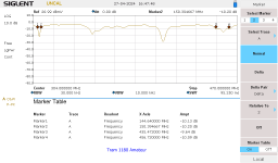
I've been running scans on a number of Dual Band VHF/UHF (including 2 meter/440) mobile antennas mounted on a NMO counterpoise for evaluation and possible fine tuning that most seem to need. These tests were done in a FULL sized attic, NOT just a crawl space, that I confirmed did little to affect the scan compared to mounting it outside the roof thru a 'roof hatch' door. (no, I'm not kidding)

Can those scans be interpreted into a more meaningful VSWR number?

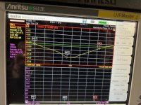
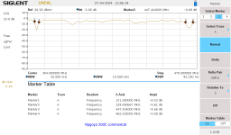
What I been doing is using a -10db figure to mark the bandwidth of the 'dips' for each band (see attachments). I choose that since anything less is really meaningless and any greater most of these would fail. Reading up on SA use and antennas, I'm under the impression that a 20db drop is a good figure with a -30 being optimum. Feel free to correct that and add any other input.

These models I choose, except for the Comet (which was the most expensive and the worst performer based on the UHF 'notch' drop), the others being Browning/Tram and Nagoya.

I hope all of that makes sense.
;)
(ignore the 'uncal', it's not relevant here)
05a Nagoya 200C.png11a Tram 1180 147 -21 447 -17.png
 

videobruce

Member
Premium Subscriber
Joined
Jan 5, 2004
Messages
456
Location
Buffalo NY
Before anyone asks, I like doing research and I do so during purchasing and after. Besides it's a learning experience and posting here is a possible service to others. Besides, you can't ever have enough test equipment. ;)
And this shows just how much these importers lie or at least 'stretch' the actual facts about the product.
 

videobruce

Member
Premium Subscriber
Joined
Jan 5, 2004
Messages
456
Location
Buffalo NY
From my understanding tiring to get anything better than a 1.3 to 1 which would be a return loss around -17db is a waste of time?
And a loss of -14 is probably more than enough; 1.5 to 1.
 

mmckenna

I ♥ Ø
Joined
Jul 27, 2005
Messages
25,591
Location
United States
Not sure it's a waste of time for hobby type use. With some effort you may be able to get it lower, but unlikely you'll notice any difference. Unlike what some CB folks think, the radio will not go up in a miniature mushroom cloud if the SWR is high (and 1.5:1 is -not- high).

Due to variables, like coax length, quality, ground plane, etc. it may not be possible to get it much lower.
 

videobruce

Member
Premium Subscriber
Joined
Jan 5, 2004
Messages
456
Location
Buffalo NY
You mentioned a "50 ohm" antenna. Would a receive only (TV) antenna show differently? Not that I ever tried to measured return loss of a TV antenna.
 

KevinC

The big K
Super Moderator
Joined
Jan 7, 2001
Messages
12,658
Location
1 point
On a 50ohm antenna -14 is 1.5 so to me anything better than -14 is good.
Unless you get one of those jerk instructors in your line sweep class that insists on saying it’s-13.979 ( which it is, but EVERYONE says -14).
 

prcguy

Member
Premium Subscriber
Joined
Jun 30, 2006
Messages
16,691
Location
So Cal - Richardson, TX - Tewksbury, MA
You mentioned a "50 ohm" antenna. Would a receive only (TV) antenna show differently? Not that I ever tried to measured return loss of a TV antenna.
You would use a 75 ohm return loss bridge and if the tracking gen and spec analyzer are 50 ohm use minimal loss pads to convert the 50 ohm equipment to 75 ohm. Then you’re ready to measure 75 ohm TV stuff.
 

KF5LJW

Banned
Banned
Joined
May 15, 2021
Messages
39
Videobruce Return Loss and VSWR express the same thing. VSWR is linear from 1 (perfect) to infinity (worse case, open or short.) Return Loss is logarithmic and starts at 0 dB (worse case open or short) and counts down to -40 dB or -60 dB; lower is better. -20 dB is ten times better than -10 dB. VSWR is an antiquated term used by CB operators and antenna manufacturers to describe their antenna bandwidth.

For example, ACME antenna offers a 2-meter antenna with a bandwidth of 144 MHz to 148 MHZ @ VSWR equal to or better than 1.5 or RL = -14. That is all VSWR is suitable for. A VSWR bridge is 1950s technology, and the reading will depend on where you place the circuit in the transmission line. CB operators did not have directional couplers back then. Today, with directional couplers, all commercial radio equipment uses directional couplers to read Return Loss. It is much easier to use and understand with simple 5th-grade math. Return loss measurement is much more detailed and informative.

Your TG skills need some improvement to give you more meaningful measurements. Your scale and frequency range are out of bounds and lack detail. When you make a scan, it is not linear but divided into data points—for example, 126 or 252 points divided across the frequency band. It plots the 126 dots and draws a line to connect them on the scale. Look how wide you are scanning. You don’t give rats behind what is outside your frequency markers for 2 meters and 70 cm band. You are wasting your resolution for data you cannot use. Instead, make two scans, one for 2 meters and one for 70 cm.

For 2 Meters, set the Center Frequency = 146 MHz and Span = 5 MHz (start = 143.5 MHz, stop = 148.5 MHz. For 70 cm, set the Center Frequency = 445 MHz and the Span = 35 MHz. Instead, those skinny dips at the far ends will fill the screen with a lot of detail you have been missing.

Now, let us get your scale under control and make it worthwhile with a lot more details. Your scale is set to Top = 10dB and bottom to -90dB. That is why you see such small dips lacking accuracy and detail. The strongest possible reflection you can have is 0 dB, 100% of the power reflected at you. You have the Top set to 10 dB, wasting resolution and accuracy. Set the Top = 0 dB.

If you ever see an antenna or a dip to – 50dBm, rest assured you are looking into a precision 50-ohm calibration load, as good as it gets or perfect. Anything below -50dB is just wasting more accuracy and resolution. Start by setting the bottom scale to -50 dB and run a scan. Look at how low the antenna dips, say -25 dBm, and adjust the bottom of the scale to -30 dBm. You want that dip to fill the screen from right to left and top to bottom to maximize detail and resolution. Try it; you will like it and soon forget the term VSWR.

Below is a sweep of a 20-meter antenna. The top trace (yellow) is RL, and the bottom trace (purple) is VSWR. The Green line is a pass/fail line set to -14 dB and 1.5 SWR, respectively. Which trace tells you more about the antenna? You might need a magnifying glass to the the purple VSWR trace.

sweep.jpgsweep.jpg
 

videobruce

Member
Premium Subscriber
Joined
Jan 5, 2004
Messages
456
Location
Buffalo NY
Videobruce Return Loss and VSWR express the same thing.
Yes I know as evident of the title of this thread.
Your TG skills need some improvement to give you more meaningful measurements.
The antenna tested were all dual band. I choose that frequency range specifically so I can see how tweaking the upper and lower sections of one manufactures antennas (Nagoya) affected the other band together at once. If I choose one or the other, that wouldn't work. I also choose to show the Marker Table as reference points of the -10db points.
I was more than aware that wasn't the ideal setup for looking at each band separately.
AFA VSWR/SWR being out of date, tell that to all the cross meter manufactures and all the Hams that have one. For more than the few of us that have SA's and RLB's.
But, thanks for the rest of your post which I will digest later. (y)

BTW, I don't have a Cross Needle meter, at least not yet as many more in-depth reviews seems to give them low marks.
 
Last edited:

videobruce

Member
Premium Subscriber
Joined
Jan 5, 2004
Messages
456
Location
Buffalo NY
You have the Top set to 10 dB, wasting resolution and accuracy.
I did that purposely since I don't like squeezing that line at the top edge of the screen.
Anything below -50dB is just wasting more accuracy and resolution.
As you stated, more than 30db range is unnecessary overkill. I didn't need that amount of accuracy for this test, just a general overview.
You want that dip to fill the screen from right to left and top to bottom to maximize detail and resolution.
Understood, thou setting a maximum vertical range I've never done. I will look into that further. As I believe I already stated, the settings I choose were compromises, not ideal, but your points are valid and I do agree with most of them. ;)

Of the five dual band antennas I compared, only the Nagoya versions had (and needed) 'wiggle room to 'tweak'. But all of that is really OT.
 
Last edited:
Top