Homebrew DIY AM ferrite antenna, variable capacitor configuration

Status
Not open for further replies.

majoco

Stirrer
Joined
Dec 25, 2008
Messages
4,283
Location
New Zealand
Right, let's stop all the guesswork and duff advice - the proof of the theory in one try!

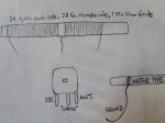
First pic - only a short ferrite rod, a turn of cardboard held in place with masking tape. 50 turns of thin insulated copper wire and a tuning capacitor marked '435pf' from the junk box. 50 turns corresponds well with that chart on my previous post.

Loop and capacitor.JPG

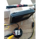
Second pic - the radio is not connected to the ferrite rod.

Near to radio.JPG

Third pic - tuned into a very faint sports programme on 1035kHz, doen't even bring up one division on the signal meter - those lines on the top left of the screen.

Untuned.JPG

Fourth pic - tuned the capacitor by ear for the strongest signal on the meter - now three bars and good clear signal of some footy match. The tuning is very sharp.

Tuned.JPG

Tuned up and down the band at each end and a good result all over. I'd say that this rough experiment was a success. No ground or coupling coil involved - the "Q" of the external antenna was so high that it boosts the signal picked up by the ferrite antenna in the radio. Now with a longer rod and tuned at the low frequency end of the band you should have even better results. Have fun!
 
Last edited:

majoco

Stirrer
Joined
Dec 25, 2008
Messages
4,283
Location
New Zealand
Now, reading back to post #1, I see you said you would like to tune the longwave band. Well, as we found when adding capacitors it's the square of the capacitor to halve the frequency. The same works for increasing the inductance to lower the frequency so in theory if we wanted the halve the low end frequency from 500kHz to 250kHz we would have quadruple the number of turns,not double. BUT there is something working in your favour for a change. The formula for inductors in series is "Lt=L1 + L2 + 2M" where "M" is the coupling between the two coils. Also in post #1 you said you had wound on 120 turns - here's what I suggest - find a turn in the middle of your coil, say turn #60. put a turn of tape either side of turn 60. Carefully, snip that turn and unwind turn 59 and 61 and twist the two ends together. If you're lucky, the insulation of the wire should be burnt off with the heat of your soldering iron, if not you'll have to sandpaper some of the insulation off - then solder the two ends together. As your two coils are almost 100% coupled via the ferrite rod then you might only need to double the number of turns. Now this 'tap' you have made should be one connection for the coil for the AM BC band, and the far end should do for the LW band. You may have to search around for a station or find some way of generating a signal. Just make sure the AM BC band works before getting too involved with the LW band.
 

PaulQ

Member
Joined
Mar 19, 2021
Messages
28
Location
Maine, US
Thanks majoco: the figures on capacitor are from datasheet. My testing gear consists of cheap oscilloscope and multimeter. Perhaps I should get a capacitance / inductance meter? I get no reading when testing resistance between any of the 3 legs on the capacitor.

Your previous notes about the high and low side of capacitor corresponding inversely to frequency reception mirror my observations.

Regarding quote below, double the number of turrns where? Making a tap as you mention creates 59 turns on each side. And am I connecting another, AM band coil to the tap? Sorry to be confused.
As your two coils are almost 100% coupled via the ferrite rod then you might only need to double the number of turns. Now this 'tap' you have made should be one connection for the coil for the AM BC band, and the far end should do for the LW band.

Lastly please, what's the best material to wrap around ferrite rod? I used paper tape with sticky side facing up, and I can't budge the coil. It's grabbed onto the ferrite bar like a boa constrictor.
 

majoco

Stirrer
Joined
Dec 25, 2008
Messages
4,283
Location
New Zealand
Hi Paul - your multimeter is not lying to you! Capacitors are supposed to be open circuit to DC but they do pass AC but not quite like a short circuit - they have "reactance" which is a bit like resistance but varies with frequency.

So you now have a coil of 120 turns with a tap at 60 turns - connect the centre leg of your capacitor to one end of the coil and one of the outer legs to the coil tap - 60 turns of the coil across the capacitor. Repeat your experiment to find the frequency coverage on your radio - if it is not sufficient, then try the other leg of the capacitor, or even join the two outer legs together, keeping the centre leg joined to one end of the coil. You might try not connecting the coupling loop to the radio, just use the same method as I did, bring a radio with an internal antenna close to the ferrite rod.

I just used a strip of card cut from a cereal packet and masking tape to hold it in place - the blue stuff in the pics. If I was going to make it adjustable I would glue the winding on to the card with PVA glue then remove or cut the masking tape so it could slide along the rod. When the 'sweet spot' is found, just drop a blob of candle wax at the rod/card junction so you cam remelt it if necessary.
 

PaulQ

Member
Joined
Mar 19, 2021
Messages
28
Location
Maine, US
Does this tap look right? There's 59 turns each side. I've tried different connections including to tap wires but the sound isn't improved when moving portable with loopstick near ferrite bar. If anything the signal deteriorates in proximity. Thanks for encouragement.IMG_31032021_184430_(1080_x_1080_pixel).jpg
 

majoco

Stirrer
Joined
Dec 25, 2008
Messages
4,283
Location
New Zealand
Yes, the tap looks alright - now show a pic of how you have connected the variable capacitor....
 

PaulQ

Member
Joined
Mar 19, 2021
Messages
28
Location
Maine, US
Here's a diagram, including how the 223p variable oscillator pins are listed on datasheet. I've tried many configurations, bringing this close to portable radio (no connection to radio). Although variable capacitor brings in more or less static, the signal overall degrades, compared to when radio is away from coil. These are the connections I've tried:
  • Common pin to either end of coil, ANT to coil tap (tried OSC also, as well as connecting OSC to ANT); other end of coil to water pipe ground.
  • Common, and one end of coil to water pipe, ANT or OSC to tap.
  • The above, but connecting ANT to other end of coil, instead of tap.
 

Attachments

  • 20210403_064736.jpg
    20210403_064736.jpg
    108.6 KB · Views: 17

majoco

Stirrer
Joined
Dec 25, 2008
Messages
4,283
Location
New Zealand
I'm wondering about your capacitor. 223pf sounds awfully low for broadcast band - I would have expected it to be about 365pF or even 500pF. I'm thinking that yours might actually be for the VHF FM band. Does it say on the spec sheet what the value is of the other capacitor and if the centre pin is definitely the common? There is no need for a water pipe ground connection, in fact it might be doing more harm than good - you can see that I didn't use one on my demo.
 

PaulQ

Member
Joined
Mar 19, 2021
Messages
28
Location
Maine, US
Hi majoco, these 223p (59.2/141.6 pf) capacitors are indicated for AM radio specifically and yes center is common.

Your excellent demo doesn't have a tap, whereas there's an open end of the coil on mine that I connect to ground (because capacitor ANT goes to tap, not other end of coil), but you're right that when removed from ground and just hanging, the signal isn't as static. It's still not an improved signal but at least not worse.
 

majoco

Stirrer
Joined
Dec 25, 2008
Messages
4,283
Location
New Zealand
So have had to join both the outer tags together to get 223pF. If I go back to that resonant frequency calculator - I know my tuner goes down to 567kHz so running that through the calculator it says that the coil is about 180uH. So your coil with double the turns might be around 400uH or more - put that back into the calculator with your 223pF capacitor and we get 532Khz! So if you connect the 120 turns of your coil across the 223pf you should be tuning around the low end of the BC band - so why didn't that work in the first instance? Connect the common to one end of the coil and the other end to the two outer connections. Pick a weak station about the middle of the AM BC band and see if it peaks up as you turn the capacitor very slowly - the peak will be quite sharp. Pity there's not a knob on the capacitor.

Hmmmm.... I'll have a hunt around in the bottomless junk box - I think there's a couple of the capacitors like yours. I'll measure them and see what value they are. If I find one that's 365pf or more you can have it - I'll let you know and if you PM me with your mail address it's yours! Hopefully the mail has speeded up a bit now :rolleyes:
 

PaulQ

Member
Joined
Mar 19, 2021
Messages
28
Location
Maine, US
Wow this is working quite the charm now, thanks for the tips. Does the twisted wire tap compromise the full-length coil?
 

Attachments

  • IMG_04042021_174311_(1080_x_1080_pixel).jpg
    IMG_04042021_174311_(1080_x_1080_pixel).jpg
    80.5 KB · Views: 15

majoco

Stirrer
Joined
Dec 25, 2008
Messages
4,283
Location
New Zealand
Well, that's great! I knew we had to get there in the end, although you were very close right at the start! We were guilty of overthinking it and adding the ground to one end of the coil completely led us up the wrong path. The tap should have no effect. Just try to establish what the frequency coverage is - you may have to adjust the number of turns on the coil - more turns to move the coverage to lower frequencies and vice versa. Have fun.
 

PaulQ

Member
Joined
Mar 19, 2021
Messages
28
Location
Maine, US
I got a new birthday toy that could help you tune or even design your own antenna.
The NanoVNA-H4, under $100, very worth it for any antenna projects to 900Mhz.
Thanks Merlin, I just watched some videos about that, which led me to discovering what a Smith Chart is, so that's cool. I installed linsmith on Linux; as I learn more, that will be a useful tool.
 

PaulQ

Member
Joined
Mar 19, 2021
Messages
28
Location
Maine, US
I've connected the modified 100-turn coil antenna, via 5-coil tap, to a 3-transistor BC548 AM receiver circuit, with high-impedance crystal earpiece. The earpiece crackles when switch is on, and voltage runs throughout the circuit, but no radio signal. Regarding tuning capacitor: middle pin is common, connected to left end of coil, an outer pin is connected to other end of coil, and outer pins are connected together.

I also tried this circuit with a 60-turn coil, no tuning capacitor, connected to circuit. Still no signal. Thanks in advance for help getting this receiver working.
AM BC548 2.jpg
AM BC548.jpg
 

PaulQ

Member
Joined
Mar 19, 2021
Messages
28
Location
Maine, US
Would someone please suggest where I might post this circuit problem to get some assistance? Thanks.
 

majoco

Stirrer
Joined
Dec 25, 2008
Messages
4,283
Location
New Zealand
Try connecting the input 10pF capacitor to the top of the coil instead of the tap - the input is high impedance and you have joined a low impedance pickup coil to it.
 

PaulQ

Member
Joined
Mar 19, 2021
Messages
28
Location
Maine, US
Thanks Martin, I'm still not getting signal after wrapping input wire around main coil. I think the antenna's fine. I've tested voltage throughout circuit, about .07v. The circuit is taken from link you posted.
 
Status
Not open for further replies.
Top