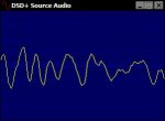
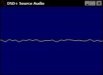
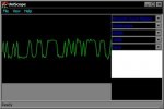
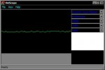
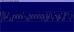
The general concept of a waveform is to show a visual representation of a value, whether it's an audio waveform, or an electrical one, etc. In your image above, the right side basically shows nothing of any use at all, barely any peaks which represent the level of the signal being passed across the discriminator tap through the Windows audio mixer - first glance at it shows it's nearly flat which would mean practically nothing at all (flat line = dead, no signal, nothing there to measure basically). When you see peaks and valleys and whatever, that's a very noticeable indication that something is going on, some type of signal is being provided to be measured as opposed to just having a flat line dead input with nothing at all.
The one on the left is significantly stronger and provides more to work with so I have to ask: are you 100% certain that you snapped those screenshots during times when both scanners were actively receiving a signal on the given frequency?
Also, the signal strength received in the scanner's tuner is not necessarily going to translate across to the discriminator tap meaning the baseband audio output is not always (very rarely actually even in spite of the idea of a tap) going to be exactly the same level. The sheer signal itself can account for a lot of variation depending on the way the scanner it handling it internally before being passed to the discriminator (that you're tapping a signal from) and turned into audio output for the scanner's speaker.
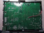
In that image, if as much as possible is duplicated - and you said it's the same antenna, same frequency/signal, and I'm going to presume that you're using the same audio input on the computer and not one of several dedicated to each scanner (which is another thing) - and those screenshots are accurate, it would be easy enough to say the BCT-15x just isn't outputting a very "loud" signal on the tap you've created - I'm not saying it's not functional because it might be, but if all the stuff between the scanner (but not including the scanner) and the waveform display - meaning the tap, the cabling, the audio input, the audio levels, the entire pathway - is the same and only the scanner providing the signal is different then obviously the difference lies with the scanner itself.
Now, what I just said about multiple inputs could be relevant as well if that's what you have in action - multiple scanners, with some kind of audio inputs like a physical mixer or multiple line or mic inputs to a computer (like one internal one then another provided by a USB-based sound card/device, etc) could account for discrepancies in signal strength and might be addressed with Windows mixer adjustments. I can't say because I don't know the full actual setup you're using.
But just from a glance, if everything after the scanner is the same and not changed, that means the scanners themselves are just providing a different level of baseband signal to work with from their respective taps.