help with yagi for wifi

Status
Not open for further replies.

AMW55

Newbie
Joined
Feb 23, 2022
Messages
0
Reaction score
0
I hope it's okay to ask about wifi antennas?

I am trying to build something for wifi for very small distance but with walls and objects that is weakening the signal

I have the following

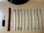
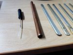
9 flat aluminum pieces (14 cm) from old uhf or vhf antenna to be used for directors and reflector

copper tube (14-15 cm) (9mm diameter) (1mm thick) to be used for driven element

and already have 2 dB antenna as coaxial

I am aiming for 2412 GHz since I use channel #1 and with the parts length I have I can do 19 elements

The best/clearest calculator and simplest design I found is this

KN9B - YAGI

But I have no clue about mixing copper and aluminum or using tube for driven and flat for directors.

Maybe put the flat directors on their edge instead of on the flat side?

What do you think of all this?

antenna.jpg1.jpg2.jpg
 

mmckenna

I ♥ Ø
Joined
Jul 27, 2005
Messages
27,163
Reaction score
32,511
Location
United States
If it's going to be used indoors only, the dissimilar metals are not an issue.

Just attach the elements flat on the copper tube. Easier to build and will work just fine.
 

AMW55

Newbie
Joined
Feb 23, 2022
Messages
0
Reaction score
0
I wanted to glue them to plastic boom, I don't have long boom made of copper, just what you see in the pic, I think I still lack the basics but I am aiming for something where there is no connectivity in the boom, the only part that is connected is the copper pipe, any idea how to attach the coaxial to the copper? any rules for that, the wire and shield to the upside and downside of the same spot?
 

mmckenna

I ♥ Ø
Joined
Jul 27, 2005
Messages
27,163
Reaction score
32,511
Location
United States
Soldering the coax to the copper pipe should be simple if you have a hot soldering iron. If not, drill a small hole and use some tapping screws.
 

AMW55

Newbie
Joined
Feb 23, 2022
Messages
0
Reaction score
0
Thank you mmckenna, I mean isn't it weird that both parts of the antenna (coaxial) touch the same copper part, doesn't that cause problems? should they at least be touching in distant places? not sure I can do that.
 

mmckenna

I ♥ Ø
Joined
Jul 27, 2005
Messages
27,163
Reaction score
32,511
Location
United States
Thank you mmckenna, I mean isn't it weird that both parts of the antenna (coaxial) touch the same copper part, doesn't that cause problems? should they at least be touching in distant places? not sure I can do that.

It depends on the type of feed you use. You can do a gamma match/hair pin match, or cut the radiator in the center and feed each side separately. You'll need to figure out which one to use, and build based off that.
 

bharvey2

Member
Joined
Mar 12, 2014
Messages
2,025
Reaction score
902
I think KN9B's instructions were a little vague with regard to the driven element instructions. The first diagram shows a dipole. As mmckenna points out, this should be cut into two separate but equal lengths of tubing. They should be separated electrically but the total length should equal the total length as calculated for you frequency. Center conductor of coax is connected to one of the halves and the braid to the other.
 

prcguy

Member
Joined
Jun 30, 2006
Messages
17,642
Reaction score
12,978
Location
So Cal - Richardson, TX - Tewksbury, MA
The element lengths will be slightly different between an insulated and conductive boom and any good Yagi calculator should also take element diameter into account. If your calculator does not have all this find another one that does.

It might be easier to make a large corner reflector which can use the feed you have. The corner reflector sides will be about 5" tall and the longer they are the more gain you will get. The angle between sides will be different for different side lengths.
 
Status
Not open for further replies.
Top