
- Forums
- Scanners, Receivers and Related Equipment Forums
- Antennas and Associated Hardware
- Build Your Own Antenna
You are using an out of date browser. It may not display this or other websites correctly.
You should upgrade or use an alternative browser.
You should upgrade or use an alternative browser.
Homebrewed Off-Center Fed Dipole question
- Thread starter Bellingham_Scanner
- Start date
- Status
- Not open for further replies.
Wirelessly posted (Mozilla/5.0 (iPhone; CPU iPhone OS 6_1_3 like Mac OS X) AppleWebKit/536.26 (KHTML, like Gecko) Version/6.0 Mobile/10B329 Safari/8536.25)
...and the dBi notation is right there on your plot. Missed it because was reading on iPhone and didn't magnify enough.
It would be interesting to see same plots for 155, 450, 700, and.800 mHz. Thought I'd ask since they are so simple and quick for you to do..... NOT!")
...and the dBi notation is right there on your plot. Missed it because was reading on iPhone and didn't magnify enough.
It would be interesting to see same plots for 155, 450, 700, and.800 mHz. Thought I'd ask since they are so simple and quick for you to do..... NOT!
I ran out of graphic space, so I'll see what I can do about that - had to squeeze that last graphic down.
For the short ocfd, at 155mhz, the plot is very similar to a center fed halfwave dipole. We've seen it at 300 and how it suffers at low angles as compared to a dipole. Some can live with it, some can't.
860mhz is ridiculous with multiple lobes and the main one near something like 82 degrees above the horizon.
For illustration, these are in free space. Over real ground, multiple pencil-thin lobes will be observed.
I just got off the phone with the marketing department, and they tell me to say:
"Our exclusive common-mode cable technology fills in the gaps that many other antennas leave behind! Digital-ready, the ocfd guarantees at least 150 more talkgroups will be heard compared to the common dipole!"
Obviously I like the ocfd a lot for what it is and have built many, but am not fooled by it...
Last edited by a moderator:
It's odd, isn't it? I mean how they always seem to hide the really good electrical/RF engineers in the advertising department...
Another word of caution about those antenna modeling programs. They certainly can give you a good general idea of how any particular antenna may radiate, but they are almost never more than a generalization of an antenna in a near 'perfect' environment. To make them really 'close' for a real life antenna you would have to enter an unbelievable amount of information which almost no one can do, or even know about. The biggy is that they all work in 'free space'/isotropic space and then you have to figure out how that relates to the 'real world'. Not impossible, but not easy either. It's a sort of mixture of field theory and geometry.
No, I'm not 'bad mouthing' antenna modeling programs cuz I use them too. I am saying that you can't take the information generated without a lot of 'modifying' to relate it to real life, can't just accept the results as 'gospel'. When you keep that in mind, they are really nice thingys to have.
- 'Doc
prcguy
Member
- Joined
- Jun 30, 2006
- Messages
- 17,855
- Reaction score
- 13,355
One of my antenna mentors (senior staff scientist at a major aerospace co and also friends of the publisher of EZNEC) stated that EZNEC will tell you precisely how an antenna will perform if you feed it all the correct parameters. Modern antenna analysis programs very mature and give accurate results.
And thank you hertzian for taking the time to run the numbers.
prcguy
And thank you hertzian for taking the time to run the numbers.
prcguy
It's odd, isn't it? I mean how they always seem to hide the really good electrical/RF engineers in the advertising department...
Another word of caution about those antenna modeling programs. They certainly can give you a good general idea of how any particular antenna may radiate, but they are almost never more than a generalization of an antenna in a near 'perfect' environment. To make them really 'close' for a real life antenna you would have to enter an unbelievable amount of information which almost no one can do, or even know about. The biggy is that they all work in 'free space'/isotropic space and then you have to figure out how that relates to the 'real world'. Not impossible, but not easy either. It's a sort of mixture of field theory and geometry.
No, I'm not 'bad mouthing' antenna modeling programs cuz I use them too. I am saying that you can't take the information generated without a lot of 'modifying' to relate it to real life, can't just accept the results as 'gospel'. When you keep that in mind, they are really nice thingys to have.
- 'Doc
I couldn't have said it better!
They are however close enough to let me know when I'm going in the wrong direction with time, money and materials.
Free space is nearly always an unrealistic ideal, so using a ground (either real or mininec) is always recommended and of course calibrated to your own ground if you have a way to measure it.
One thing many may not include is the affects of common-mode cabling. Once done modeling the antenna elements themselves, try attaching 30 feet or so of "wire" to one side of your antenna elements simulating a coaxial cable shield, and do another plot. Depending on a number of factors, the skewed directional results may be surprising. This is one real-world factor that many forget to include especially on hf.
But yes, there is the temptation to get so focused that all you ever do is model, and never put up anything outside and try it and discover that your modeling is in error, or that you are obsessing over factors that don't make a real-world difference..
The OCFD makes a neat little project for EZnec, even the demo version which handles small non-complex antennas just fine.
And thank you hertzian for taking the time to run the numbers. prcguy
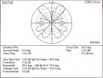
My pleasure! Here is a plot of the "shorty" ocfd (2ft and 9-inch leg) in free space at 860 mhz! The standard version (4ft / 18 inch legs) is even worse!
OUCH! But, if you are in a total rf-jungle, have a scanner that easily overloads, this built-in directional attenuation may not be so bad. For me that would have to be REAL bad.
Attachments
Last edited by a moderator:
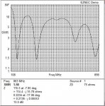
SWR plot - here are the resonant peaks of the shorty ocfd at about 150mhz, 330mhz, 650mhz, and 868mhz.
These values are *without* the 4:1 tv-type transformer, and the values are a bit better with the transformer.
When compared, we see that resonance does not automatically mean that you have a good antenna pattern - although real-world use depends upon environment and need.
DPD productions has nothing to fear here.
Attachments
This kind of illustrates that impedance match is not the only criteria. Milair fans may especially want to try their hand at the 24-inch / 9-inch smaller version. The smaller version has a better angle, but obviously not as good as a dipole...
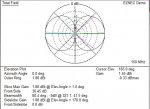
Here is the original long version in free space at 300 mhz with 4-foot / 18-inch legs. Note that maximum gain is downwards.
I assume that pattern was with the long leg down?
Would putting the long leg up reverse the pattern? (Maximun Response UP?)
Does the program calculate the DI? (Directivity Index?)
Last edited:
Actually that pattern at 300 mhz was with the long leg up! It improves a great deal if you mount the short side up to being just above the horizon.
BUT - that is at 300 mhz. When you slide around the milair spectrum, say at 250mhz with the short side up, we are back to the antenna basically pointing downwards again. Ugh!
That's the problem with ocfd's on anything other than the primary frequency - the lobes will hurt you depending on frequency, especially on a wide band like milair. The ocfd on milair is what I'd call a "fun" antenna. If you want to get serious, start out with a fat half-wave made out of tubing. (which by itself as a half-wave, can be fed in the center, or offset by 1/3 if you use a transformer)
As for the directivity index I'm not sure as I've only seen that in use with audio transducers. Perhaps it has one, but I may have missed it.
Last edited by a moderator:
Yea, sounds like a fun antenna to play with. So, from your plots, looks like for 150 / 300 the "best" OCFD is 24"/9" with the long leg up.
Other frequencies would require other lengths, orientations, length ratios, etc.
Acoustic transducers is where I work
Looked up dBi and see that it is DI.
Dipole is DI=2.15, the you show 150 MHz at 1.88 dBi That is pretty darn good!
I think I will check out the EZNEC program.
Thank you
Other frequencies would require other lengths, orientations, length ratios, etc.
As for the directivity index I'm not sure as I've only seen that in use with audio transducers. Perhaps it has one, but I may have missed it.
Acoustic transducers is where I work
Looked up dBi and see that it is DI.
Dipole is DI=2.15, the you show 150 MHz at 1.88 dBi That is pretty darn good!
I think I will check out the EZNEC program.
Thank you
The "shorty" ocfd is an improvement, but make no mistake - at anything other than the primary lower resonance, milair and above is a crapshoot unless you live in or around the flight path of a military installation where merely being so physically close to the planes overrides the funky antenna pattern.
That's the deceptive problem with the ocfd as a first-time antenna. It can be a major improvement over a rubber duck but if that is your only reference, especially since it is typically mounted high - preferably outdoors, but you'll never know how much better life is when compared to an industry standard half-wave dipole built for the band of interest.
Once one builds a standard reference antenna like a half-wave dipole for the center of the band of interest, (468 / f Mhz = total feet - either center fed directly with coax, or fed 0.33 from one end with a 4:1 300/75 ohm transformer) and then places the general purpose ocfd back up for comparison, you'll say one of two things:
1) Eh, this general purpose ocfd works ok for my needs since I'm swamped with rf already.
or
2) WHAT WAS I THINKING???
Last edited by a moderator:
- Status
- Not open for further replies.
Similar threads
- Replies
- 2
- Views
- 287
- Replies
- 3
- Views
- 841
- Replies
- 31
- Views
- 2K