• To anyone looking to acquire commercial radio programming software:

    Please do not make requests for copies of radio programming software which is sold (or was sold) by the manufacturer for any monetary value. All requests will be deleted and a forum infraction issued. Making a request such as this is attempting to engage in software piracy and this forum cannot be involved or associated with this activity. The same goes for any private transaction via Private Message. Even if you attempt to engage in this activity in PM's we will still enforce the forum rules. Your PM's are not private and the administration has the right to read them if there's a hint to criminal activity.

    If you are having trouble legally obtaining software please state so. We do not want any hurt feelings when your vague post is mistaken for a free request. It is YOUR responsibility to properly word your request.

    To obtain Motorola software see the Sticky in the Motorola forum.

    The various other vendors often permit their dealers to sell the software online (i.e., Kenwood). Please use Google or some other search engine to find a dealer that sells the software. Typically each series or individual radio requires its own software package. Often the Kenwood software is less than $100 so don't be a cheapskate; just purchase it.

    For M/A Com/Harris/GE, etc: there are two software packages that program all current and past radios. One package is for conventional programming and the other for trunked programming. The trunked package is in upwards of $2,500. The conventional package is more reasonable though is still several hundred dollars. The benefit is you do not need multiple versions for each radio (unlike Motorola).

    This is a large and very visible forum. We cannot jeopardize the ability to provide the RadioReference services by allowing this activity to occur. Please respect this.

Is 12gauge power-wire and 20 Amp fuse Overkill for a Stryker SR955HPC?

Status
Not open for further replies.

merlin

Active Member
Joined
Jul 3, 2003
Messages
3,131
Location
DN32su
"The Dosy TC4002-PSW was the worst of the meters I used (and the most expensive). I bought it new about 3 or 4 weeks ago and all I can say is that it doesn't seem to be working right. (That's the one that I read the "70-85W" from)."

With a lot of low end power/SWR meters, the power will show combined forward and reflected power.
Terminated with a 50 ohm dummy load should read closer to actual power from the radio with zero power reflected.
 

wingclip

CREEPER
Joined
Jun 16, 2022
Messages
26
Location
HOUSTON, TX.
Thanks Merlin, but I'll admit that my eyes aren't what they used to be and I could have misread. However, that alone wasn't what made this $200.00 to $280.00 meter bad, (IMO). Regardless of what the SWR, RF Power, etc., etc., was, the repeatability for the meter to react to the input, was definitely one of the issues that made me doubt it's integrity.

In addition, the face-plate of the Dosy meters that they sell now, are labeled with a very low-quality silk-screen process that leaves the text to appear blurry and faded. In fact, I think that these Dosy meters are not at all of the same quality they were 15 years ago! I say that because there are many people who have placed pics of their Dosy meter in forums and show a huge difference in the quality of the labeling.

After I received mine and saw the poor labeling (and performance contradictions), I asked several people who displayed pictures of their when they bought their meters, (TC4001, TC4002, TC3000, etc., online), only a couple answered. Those that did answer said they barely could remember how long ago it was, but they guessed at least 10 years.

I think MmcKenna said it all when he pointed out how the Workman's and several other well known brands 'back in the day' are now cheap shadows of what they once were, due to corporate buy-outs, relocations, etc.

I think that explains it for the Dosy line today. That also explains why there were many who swore by them, but agreed that the Dosy line today is not the same as the line that were manufactured years back. In any case, I'm selling my Dosy TC4002-PSW ASAP.

I'll probably put it up for auction (or try to sell it outright for about $180). Even though it's in the same pristine condition it was in when I got it, I doubt I'll get what I paid, (about $220), if I go with the auction.
Thanks again,
Rich
BTW; Do you happen to know what a good battery-post attachment method (or maybe a clamp?), is for adding a 12-gauge (or maybe 8-gauge) power wire would be?
 

mmckenna

I ♥ Ø
Joined
Jul 27, 2005
Messages
25,297
Location
United States
BTW; Do you happen to know what a good battery-post attachment method (or maybe a clamp?), is for adding a 12-gauge (or maybe 8-gauge) power wire would be?

Look at the existing battery clamp. There is almost always a bolt holding the clamp on. You can put a ring terminal under that bolt.
Some may also have an additional threaded stud that can be used. Usually a metric nut (6mm x 1) will work.
 

wingclip

CREEPER
Joined
Jun 16, 2022
Messages
26
Location
HOUSTON, TX.
Ahh! Of course! What the heck was I thinking?! (Don't answer that).
Thank you, I ran out of some of the hardware I used to have for the job so I just ordered some quality stuff. I should have this wrapped up pretty quick as soon as the order gets here tomorrow or Monday.
Rich
 

mmckenna

I ♥ Ø
Joined
Jul 27, 2005
Messages
25,297
Location
United States
Ahh! Of course! What the heck was I thinking?! (Don't answer that).
Thank you, I ran out of some of the hardware I used to have for the job so I just ordered some quality stuff. I should have this wrapped up pretty quick as soon as the order gets here tomorrow or Monday.
Rich

Sounds like you are doing a proper job on this. It takes a bit longer, but it really does pay off in the long run.
 

wingclip

CREEPER
Joined
Jun 16, 2022
Messages
26
Location
HOUSTON, TX.
Well, you're right again. It's taking longer, LOL. I decided to go with the high quality 10GA stranded & tinned copper wire. The wire is very pliable, not at all stiff!

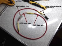
I included a picture of the Positive side of the plug, which I finished, (first pic). I need to wait until daylight before I can finish it. I have to decide how long to cut the negative side wire.

I want to check different places in the Jeep with my DVMM and confirm a good, ground point to connect that negative wire. Than I can cut it, splice it to the plug like I did with the positive, and try it out!

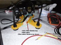
There's a few new products for splicing wire that weren't available the last time I needed to do a job similar to this. I've included a picture of these "Solder Seal Wire Connectors" (2nd pic). If you look at the second picture, you'll see the 12GA/10GA version that I used.

I didn't really trust them entirely because I never used them, so before I spliced the 12GA fuse and plug wires to the 10GA wire, I cleaned and tinned all the connection points. I made sure the ends of both wires were overlapping and then centered the solder-ring of the connector on the overlapping wires.

I heated it up quite a bit with the heat-shrink gun, (per instructions from the manufacturer), and I can only guess that it was hot enough to melt that solder-ring and create a good bond. I pulled on them pretty hard and they didn't come loose, so...

I also slipped an additional heavy heat-shrink tube over each splice connector for extra insulation, (as shown in the first pic). Once I get the negative wire together, I'm going to add a long piece of heavy heat-shrink tubing over the positive and negative wires.

That'll hold them together so that the tubing covers the wires from the base of the plug, and run on down for about 6" or 8".

Like I said, it feels like a strong connection and of course, I tested the continuity and resistance, (all good).

Power-Wire-rig-A-(flat).jpg

Power-Wire-rig-B-(flat).jpg

Rich
 

mmckenna

I ♥ Ø
Joined
Jul 27, 2005
Messages
25,297
Location
United States
The high strand count wire is nice stuff. I use an SAE rated cable in my installs, and it has a lot of very fine strands that make it super flexible and nice to work with.

I've never tried those sort of butt splices. I was skeptical that the wire/solder would get hot enough to actually flow. I usually avoid the butt splices and just run a solid run of wire from the breaker at the battery to a fused distribution block, but that's for multi-radio installs and would be overkill for what you are doing.

The heat shrink really makes it look good. I use quite a bit of it when I do installs.

When this is all done, you'll be way out in front of 99% of the CB users. Putting the effort in does take a lot of extra time, but never having the radio give you any problems is well worth it. Plus, I usually enjoy that sort of work.
 

wingclip

CREEPER
Joined
Jun 16, 2022
Messages
26
Location
HOUSTON, TX.
Thank you, Mmckenna!
"Plus, I usually enjoy that sort of work." I must confess that I get the same pleasure from doing this as you do! In fact, I have an inexplicable fascination with the field of electronics. I mean, a seriously strange draw to how the science in this field works!

It’s a hobby (among many of my hobbies), that I try to apply my time. I’ve joined with several online electronics websites, but when it comes down to it, it’s still way over my head.

Over the years, I don’t even want to admit to the money I’ve spent trying to get a grip on the way a motherboard works, or even worse, the subject of "RF frequencies"!

I have Spectral Analyzers, Oscilloscopes, AC multimeters, (and many others I won’t even name), and I still haven’t learned the rudimentary applications of these instruments, let alone what they're actually telling me!

I’m simply not applying enough time in this field to even understand the basics. But I’ve recently changed a few things in my scheduling and opened up at least 2 to 3 hours a week where I can do some very real “back to the basics” studying.

It’ll certainly keep my mind working and even if I never really catch on, it’s still just a fascinating field to delve into!
Rich
 

wingclip

CREEPER
Joined
Jun 16, 2022
Messages
26
Location
HOUSTON, TX.
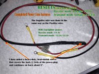
WOW! The direct power connection with the 10GA wire made a HUGE difference! Even my receiving volts went up. Now, the receiving voltage is 14.6V and transmit voltage is 14.4!

This is the harness:
Completed-Harness-B-(flat).jpg

Then came time to connect it to the battery and the ground to a prepared metal surface… Every test with my DVMM indicated the battery box had the best resistance and continuity readings. So, I attached the negative wire there. I
sanded the painted surface to bare metal. It’s a cramped area to work in and I expected some trouble getting the ground wire attached. I applied a high-temp resistant silicone sealant over the connection as a precaution.

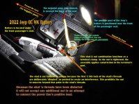
It turned out that the positive wire that was the real problem, (and still is, but just for now). I have it temporarily attached to the positive post so I could do the tests, (2nd pic). The results were FAR better than I expected and proved that this was well worth the trouble!

With the cigarette lighter plug & 16GA wire for power, I was getting 14.3v/14.4v in receive mode and 12.3v to 12.4v when I transmitted. NOW, I get 14.6V in receive mode and 14.35V when transmitting! (Bounces between 14.3V & 14.4V).

Special-Battery-Clamp-Screw-(flat).jpg

The Positive wire connection problem:
In the 2nd picture, you can see the positive terminal clamped to the battery’s + post, but the clamping method they used is an offset 6mm stud & nut system.

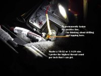
My plan was to fasten the positive wire to that 6mm stud with an additional lock washer and nut. But then I found that the first 1/8” of threads in the 6mm stud was deliberately peened or dimpled!

I can’t unscrew the nut from the stud and the stud won’t unscrew from the section it’s threaded into, (both ends were probably peened). Of course, I can’t add a 6mm nut to the stud unless I chase the stud’s threads with a 6mm thread die.

But my thread-dies are too large to fit in that tight area. I maybe could find a cheap 6mm die with a major OD of no more than ¾” but I think I’ll use another way. The alternative is to drill and tap a hole in the terminal where it’s safe and clear of obstructions, (the 3rd picture).

Alternate-Pos-location-(flat).jpg

Because that section of the terminal isn’t very thick, I’d want a fine-thread screw. At the moment, a 10-32 looks like a good choice but it’s not quite as big as I’d like.

The 6mm screw has 25.4 threads per inch whereas the SAE ¼-28 screw has more threads and it’s larger than a 10-32. I haven’t decided on what I’ll do just yet.

Still, I can’t get over how much better the voltage efficiency improved with a direct connection! I mean, a .2Volt drop when I transmit now compared to over 2 Volts when I used the cigarette lighter plug! (y)

I drove to the store earlier and asked for a radio check. The driver who answered came back loud and clear and he was driving away from my location. We established that we were at least 10 or 12 miles apart and he wasn’t fading in and out. I couldn’t tell that he was getting even farther away with each minute we talked.
Rich
 

mmckenna

I ♥ Ø
Joined
Jul 27, 2005
Messages
25,297
Location
United States
Still, I can’t get over how much better the voltage efficiency improved with a direct connection! I mean, a .2Volt drop when I transmit now compared to over 2 Volts when I used the cigarette lighter plug! (y)

Glad it's working.
A lot of us try to point this out to newcomers, but the cheap sexiness of a quick and easy install using a cigarette lighter plug is just too alluring for some.
"Why do it right when you can do it quick"
You know the difference now, and you can help us lead new users to the light.

One option is to use a fork terminal on the positive wire. Tuck it under the existing nut.
If that is not going to work, then drilling a hole and tapping it, or at least a nut, bolt and washers is a good option.

I drove to the store earlier and asked for a radio check. The driver who answered came back loud and clear and he was driving away from my location. We established that we were at least 10 or 12 miles apart and he wasn’t fading in and out. I couldn’t tell that he was getting even farther away with each minute we talked.
Rich


That sounds like it is working really well.
Clean power directly off the battery really makes a difference. So many leave all this performance sitting on the table because they can't, or won't put the effort into doing a proper install.

Now if we can just get you to see the light on antenna installs, we'll have fully converted you over to our side.
 

mmckenna

I ♥ Ø
Joined
Jul 27, 2005
Messages
25,297
Location
United States
The amateur radio, CB, GMRS, scanner hobbies would be so much improved if auto manufacturers stopped installing cigarette lighter plugs in vehicles. I know, major inconvenience, but forcing people to do an install correct would be a good thing.

It's almost like there's a reason public safety vehicles are set up this way. It's almost like the people doing the installs actually know something.
 

wingclip

CREEPER
Joined
Jun 16, 2022
Messages
26
Location
HOUSTON, TX.
"One option is to use a fork terminal on the positive wire. Tuck it under the existing nut.
If that is not going to work, then drilling a hole and tapping it, or at least a nut, bolt and washers is a good option."

No, the nut will not offer any gap whatsoever between it and the clamp-block. In addition, the peened stud keeps any additional nut from threading over it.

Over the years, my work history included several trades and skills. However, my main “fallback trade” and expertise was as a machinist, (1st class Job shop 23+ years). I’ve seen just about every kind of thread and thread style you can imagine, including the interference method used on this 6mm stud.

They distort a section of the threads using one of any number of various techniques to keep a normally threaded nut from threading past a given section in the stud, (or an additional nut from threading on it, as is the case here).

This method (peening or dimpling) is a fast and cheap way to create an interference thread. It’s used in non-critical applications but for larger fasteners and more important applications, a far more precise technique is used.

"Now if we can just get you to see the light on antenna installs, we'll have fully converted you over to our side."

LOL, you have a better chance of convincing me to sprout wings and fly than you do in trying to get me to drill a hole any larger than 1/32" (the size of the hole I drilled in the battery box) into the body of that $60K Jeep! I looked at hood-clamp antennas but the risk of bending the metal at the clamping area was too great.

Besides, the SR A-10 Mag-Base that Stryker makes today comes with an RG8X coax. I know of the the direct-mounted antennas and the better results, but the ground plane of the A-10 is quite sufficient for CB mobile. W/O skip, I regularly get out between 10 and 20 miles, no problem.

When you consider that the roof of the 2022 Jeep, (with 22" Tires), is 6'7" and the A-10's whip is another 5 feet, (not counting the 7.5" base), it's over 11.5 feet high.

I don't need convincing that there are better antennae and mounting methods for mobile, I'm already well aware of that. Way back in my early CB years, (circa 1974), on through to my OTR/48 truck driving years, (1990-1996), I picked up a lot about increased efficiency via antennas.

I even knew it was better to make a direct power connection for the radio way back then. It's like you said about "quick" being the go-to method more often than not. However, I must admit that I was surprised at how much more improved the direct power connection was! I only expected (and dared hoped for) about a 1 volt improvement, so yes, this direct power was definitely worth the effort.

But the A-10 serves its purpose well. Keep in mind that I bought the Jeep new, less than a year ago and it hasn't even got 1700 miles on it. If I ever get around to earning a Ham operator license (and that's a very real possibility), and I get a "big radio", I'll very likely go with a much better antenna rig.

Perhaps more importantly is the fact that I can easily unscrew the A-10's coil, cap off the threaded receiver with the cap Stryker included with the antenna, (which has an O-Ring seal), and go through the car wash.

Then, when I screw the coil back on the receiver in the mag-base, the SWR is right where it was before. No retuning!

So to recap; 11.5+ feet high, Easy to disconnect/reconnect w/o SWR loss or retuning, RG8X coax, and most importantly, NO HOLES.
You have to admit Mmckenna, those are pretty good reasons for sticking with the A-10, no?
Rich
PS Thanks for the help and encouragement!
 

mmckenna

I ♥ Ø
Joined
Jul 27, 2005
Messages
25,297
Location
United States
It's your car, you do what you feel most comfortable with.

About 2 or so years ago, I did a permanent NMO install on a $75K Chevy truck. It was a family members truck, and he brought it straight to me from picking it up at the dealership. So, showroom to my driveway in about 30 minutes, then the drill came out. I think it had 24 miles on the clock.

You can get NMO mounts with better coax than RG-8x. LMR-200 and LMR-240 are options.

You can also get NMO rain caps that screw on the NMO mount and seal it for car washes.

You won't get any flack from me regarding this. It's your vehicle, your choice. It does work better, but it's a big step for some. The improved DC power feed will help a lot, as you've seen. If you decide to do a permanent antenna mount down the road a few years, we'll be here for you.
 

wingclip

CREEPER
Joined
Jun 16, 2022
Messages
26
Location
HOUSTON, TX.
If you decide to do a permanent antenna mount down the road a few years, we'll be here for you.
You can bet on it! However, after I check with you, I'll probably take it to an expert like yourself because it would need to be done professionally. (Not by someone like me who's never done it at all! :rolleyes:) Thank you!
 

KMG54

Active Member
Premium Subscriber
Joined
Apr 24, 2011
Messages
1,291
Location
Easley S.C.
Your wiring harness looks great. I am not sure about he but connectors though. I am sure they will work. As a master certified Auto Tech, all my splices are done with tinned wire and uninsulated copper butt connectors using ratcheting crimpers, a second solder job and marine adhesive heat shrink. But hen again, I am working with 5 volts at really low milliamps.
 

Project4

Member
Joined
Sep 13, 2011
Messages
30
Location
40.780346,-119.229984
I have a 2016 WK2. Under the hood, curbside and a short distance from the firewall is a shrouded post provided by Jeep for attaching jumper cables. This hexagonal post is under a RED plastic cover. If your Jeep is equipped similarly, you can remove the post from its threaded stud, place a suitable ring terminal on the stud and replace the hexagonal post. I ran 4 AWG cable from the post to the cabin interior near the passenger kick panel. From there the cable continues to the rear cargo compartment with taps at the bases of the front and second row seats. It was important to minimize the voltage drop to the rear to accommodate a Micom HF radio and an XTL5000 high power VHF radio. The circuit is protected immediately downstream from the hexagonal post by a "Maxi-Fuse" blade. Negative cables from the radios go to nearby chassis ground points.

Within weeks of delivery, my GC had two holes in the roof, occupied by Larsen NMO antenna mounts. My previous new car, a 2001 Ford Excursion had seven. (Disclosure: The Excursion and the Jeep together added up to about what you paid for your Jeep). Installed correctly, the hard antenna mounts will not harm your roof; Don't be skerred. The first time a tire slides off a wet rock, the "new" will fade from your car anyway :)

Enjoy your Jeep and your Stryker.
 
Status
Not open for further replies.
Top