Well, your connectors look like they fail IMHO and cheap coax that might pass on VHF is awful for UHF. Coax can pass the continuity test, but a pinch or hard bend effects it worthiness.problem with the connector, or damaged coax

- Forums
- Scanners, Receivers and Related Equipment Forums
- Antennas and Associated Hardware
- Coax Cable and Connectors
You are using an out of date browser. It may not display this or other websites correctly.
You should upgrade or use an alternative browser.
You should upgrade or use an alternative browser.
Is this considered professional and is it hindering performance?
I was originally going to get an adapter, however I read they created loss in the system and also could not seem to find a quality one until recently on The Antenna Farm where they have some from Lands Precision.You could have done the initial testing by purchasing a BNC to Mini-U adapter to see if it would have done the job for you and saved a bunch of $ and time. If it did, then you could have researched a shop to replace the BNC and you would have also had a previous baseline.
I have a new NMO mount with coax and a small tube of grease that is I guess what you're describing that came with a Motorola antenna I previously purchased. But it's still the same cable as what is on the truck now, RG-58/U. Which it seems is the type of coax used for all the NMO mounts. I don't know where the grease is supposed to be applied? To the outer threads of the mount and rubber gasket?TBH, I would start with a new Motorola antenna kit and replace everything. A bit pricy, but you get your moneys woth.
A properly fited mini-UHF connector on quality coax, and new NMO with everything for a professional install.
You get instructions with that, a new rubber seal, a packet of #4 compound.
Now you have a choice of antennas and location to rework the mount. UHF is not to picky mounting on corners with short distance at least 6 inches for ground plane. Cut the antenna long by 1/4 inch. You can use any quality SWR meter as long as it is designed to cover up to 800 MHz. Trim the antenna as needed for that sweet spot.
If the other NMO mounts don't leak, dont mess with them, you can put weather caps on unused mounts.
Just my way of doing it.
Last edited:
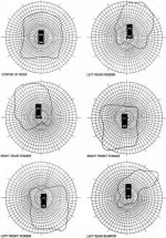
So I tested continuity today between the center pin on the connector to the center pin on the mount and there is continuity, also tested outer threads of the mount to outer shell of the connector and there was also continuity, I also tested it vise versa where there shouldn't be any and there isn't. I'm still waiting on the SWR meter to arrive so once that comes in I will test the SWR. So I guess that narrows it down to either a high SWR or a directional radiation pattern based on the location of the antenna. I found this online and found it to be interesting. It seems like the location does make a significant difference in the diagram. But I believe this was for CB frequency's so with UHF it may not be as drastic.A half wave antenna on a proper ground plane is not a unity gain antenna. It's going to have about 2.4dB of gain compared to the 1/4 wave. The 5/8th's wave will have about 3dB of gain compared to the 1/4 wave. So I'd not expect a big difference between those two antennas.
But obviously something isn't working.
A less than ideal ground plane isn't going to give you really high SWR. It's not ideal, but your SWR should be pretty good on that setup. You'd want about 6" in all directions under the mount to be ideal.
I think there is either a problem with the connector, or damaged coax. Do the test I suggested above and let us know what it shows.
Attachments
mmckenna
I ♥ Ø
So I tested continuity today between the center pin on the connector to the center pin on the mount and there is continuity, also tested outer threads of the mount to outer shell of the connector and there was also continuity, I also tested it vise versa where there shouldn't be any and there isn't. I'm still waiting on the SWR meter to arrive so once that comes in I will test the SWR. So I guess that narrows it down to either a high SWR or a directional radiation pattern based on the location of the antenna. I found this online and found it to be interesting.
OK, that means your connector, cable and mount are not likely the issue.
I would not go swapping out parts, including the NMO mount, until you know what the actual cause of the issue is.
The SWR meter will be a good test. One thing that we haven't talked about is that some NMO antennas don't seat all the way down and allow the center pin to make good contact. The SWR meter will tell you if there's an issue there.
It'll also let you know of the antenna is OK.
Lopsided radiation pattern can certainly be an issue, but I don't see a huge problem with what you have.
Sounds good, I already have a quality custom made jumper wire and adapter I ordered from The Antenna Farm to use with the meter so once it comes in we will test the SWR and see if its way out of whack, I'll also test it on the mag mount and see if its noticeably lower before making any adjustments to the antenna. Is there a "consumer priced" meter to see what my radiation pattern is or is that lab grade equipment?OK, that means your connector, cable and mount are not likely the issue.
I would not go swapping out parts, including the NMO mount, until you know what the actual cause of the issue is.
The SWR meter will be a good test. One thing that we haven't talked about is that some NMO antennas don't seat all the way down and allow the center pin to make good contact. The SWR meter will tell you if there's an issue there.
It'll also let you know of the antenna is OK.
Lopsided radiation pattern can certainly be an issue, but I don't see a huge problem with what you have.
nd5y
Member
Not as much loss as your coax.I was originally going to get an adapter, however I read they created loss in the system
What kind of coax would be superior than the RG-58U I am currently using? I know that LMR stuff is better but I can't seem to find a NMO mount that uses anything besides RG-58.Not as much loss as your coax.
If you think the radiation pattern is the issue just find a spot where it's bad then reposition the vehicle 180 degrees and see how it sounds.
mmckenna
I ♥ Ø
What kind of coax would be superior than the RG-58U I am currently using? I know that LMR stuff is better but I can't seem to find a NMO mount that uses anything besides RG-58.
You can pay extra and get LMR-200 or LMR-240.
But, it's not going to fix your issue, and it's not going to make a noticeable improvement. LMR-240 is also kind of stiff, has a bigger bend radius, and is a stone cold b!!ch to run in a vehicle. You'd see a tenths of a Decibel improvement, and that's not going to be noticeable.
I run an 800MHz trunked system with a lot of mobile radios. Cable losses go up with frequency, and even in that application, we use RG-58. Just not worth the cost or installation challenges to squeeze out that improvement that would never be noticed.
mmckenna
I ♥ Ø
Is there a "consumer priced" meter to see what my radiation pattern is or is that lab grade equipment?
Field strength meter is what you want. Not worth the cost of the tool, it would take a while to be proficient with it, and interpreting the results would just give you the same info as on the chart you posted.
Wait and see what your SWR meter tells you.
Not sure what NMO mount you are using on the roof, but hopefully it's the one in the center.
Good to know!You can pay extra and get LMR-200 or LMR-240.
But, it's not going to fix your issue, and it's not going to make a noticeable improvement. LMR-240 is also kind of stiff, has a bigger bend radius, and is a stone cold b!!ch to run in a vehicle. You'd see a tenths of a Decibel improvement, and that's not going to be noticeable.
I run an 800MHz trunked system with a lot of mobile radios. Cable losses go up with frequency, and even in that application, we use RG-58. Just not worth the cost or installation challenges to squeeze out that improvement that would never be noticed.
I was using the one on the driver side. The middle one is for my scanner, which frankly I will use more than the radio. If you think it would be better to still put the UHF radio antenna in the middle I can and then buy an adapter for BNC to mini UHF till it can get swapped.Field strength meter is what you want. Not worth the cost of the tool, it would take a while to be proficient with it, and interpreting the results would just give you the same info as on the chart you posted.
Wait and see what your SWR meter tells you.
Not sure what NMO mount you are using on the roof, but hopefully it's the one in the center.
That's why I was concerned with the ground plane since it was in that corner.The only other difference was the antenna placement. Originally it was on the mag mount in the center of the roof and that connector now goes to the driver rear corner. I also know that that location probably doesn’t provide an adequate ground plane for a 5/8 wave so I tried using a NGP and the results seem the same.
I hadn't thought of that, if the SWR test well I will definitely try that!If you think the radiation pattern is the issue just find a spot where it's bad then reposition the vehicle 180 degrees and see how it sounds.
And truthfully, I chose that corner because it allowed me to chop off several feet of excess coax cable since I had read that the shorter the cable, the less loss there would be.Good to know!
I was using the one on the driver side. The middle one is for my scanner, which frankly I will use more than the radio. If you think it would be better to still put the UHF radio antenna in the middle I can and then buy an adapter for BNC to mini UHF till it can get swapped.
That's why I was concerned with the ground plane since it was in that corner.
N4DES
Retired 0598 Czar ÆS Ø
I was originally going to get an adapter, however I read they created loss in the system and also could not seem to find a quality one until recently on The Antenna Farm where they have some from Lands Precision.
Nothing that you would have ever noticed, and you would have avoided going through the expense and drama you have had so far.
This is all true. Looking back I should have just got a quality adapter, I still can change the antenna to another one the mounts and get an adapter.Nothing that you would have ever noticed, and you would have avoided going through the expense and drama you have had so far.
Another thing to note is that the mag mount is only a 12 foot coax cable while the NMO uses a 17 foot coax. I don't know how much of a difference that makes in terms of loss but its something to point out, the mag mount being centered in the roof with a shorter coax vs being on a mount that's on the corner of the roof with an extra 5 feet of coax.And truthfully, I chose that corner because it allowed me to chop off several feet of excess coax cable since I had read that the shorter the cable, the less loss there would be.
mmckenna
I ♥ Ø
I think you are getting way too hung up on this coax loss thing.
It's not as big an issue as you are thinking. I'd move the Motorola radio onto the center NMO, that would help your radiation pattern. Chopping 5 feet off your RG-58 is going to have a few tenths of a dB improvement, and again, that's not going to be noticeable unless you are on the very fringes of coverage.
Same with adapters. Yes, not using adapters is better than using one, but it's really somewhere around a tenth of a dB for a good quality adapter. The Lands Precision you mentioned at Antenna Farm should be good quality. I think I've used that brand before and I don't recall any issues.
Ubbe
Member
I think it's a misconception among HAMs and we who work professionally with connectors and adapters have no issues using adapters. You can't measure any loss, or less than 0,1dB, at the frequencies we use below the microwave bands. It probably origins from a HAM using RG58 and could have had some water ingress in an adapter that wasn't water protected properly and when replacing it with a whole length of coax he used LMR240 or LMR400 and thought it must had been an issue using adapters.I was originally going to get an adapter, however I read they created loss in the system
/Ubbe
G7RUX
Active Member
- Joined
- Jul 14, 2021
- Messages
- 690
- Reaction score
- 425
Is there decent continuity between the mount threads/coax screen and the vehicle bodywork? A common cause of performance issues with a through-body mount is the lack of decent continuity there leading to poor antenna performance.So I tested continuity today between the center pin on the connector to the center pin on the mount and there is continuity, also tested outer threads of the mount to outer shell of the connector and there was also continuity, I also tested it vise versa where there shouldn't be any and there isn't. I'm still waiting on the SWR meter to arrive so once that comes in I will test the SWR. So I guess that narrows it down to either a high SWR or a directional radiation pattern based on the location of the antenna. I found this online and found it to be interesting. It seems like the location does make a significant difference in the diagram. But I believe this was for CB frequency's so with UHF it may not be as drastic.
Similar threads
- Replies
- 8
- Views
- 878
- Replies
- 12
- Views
- 749