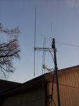
My homemade Off Center Dipole Antenna

Status
Not open for further replies.

popnokick

Member
Premium Subscriber
Joined
Mar 21, 2004
Messages
2,841
Location
Northeast PA
Still have roughly a 7 dB difference on the TV signal(470.310) which I'm using as it's more constant than the NOAA signals.

Your NOAA signal is not "constant"? That's rather odd... they are all 24/7 continuous unless something unplanned interrupts the transmitter or damages their antenna. Suggests to me that you have an intermittent connection somewhere. Also, you should be using weaker signals than a TV broadcast carrier for testing. Strong signals mask a lot of potential problems. And while it may not make a major difference, most broadcast TV signals are horizontally or circularly polarized. If you installed them correctly your OCFD antennas are vertically polarized to match the typical scanner public safety, aviation, ham, NOAA, etc. signals you are trying to receive.
 

HelixArray

Member
Joined
Jul 24, 2007
Messages
100
Location
TN
^popnokick My NOAAs are constant and up.. just not a solid dB like that TV channel. I'll stick with correct polarity from here on out.

http://i.imgur.com/v52Zcvt.jpg

http://i.imgur.com/cCLzJ0y.jpg

http://i.imgur.com/yPbfxj7.jpg

Couldn't find an insulated T-fitting for the EMT so I used a wooden dowel. The metal is cut to the Wiki length but the spacing is closer than copper versions due to not using a T-fitting.

After about 50 trips up and down the ladder I can confirm a few inches of movement is with out doubt relevant; just as you guys stated. The amount of potential outcomes seem endless for me. I take one step forward and two steps back it. Move it one way it does worse on 460-462Mhz and better on 153-154Mhz. I tested all my coax on an Aspen Eagle TV antenna (same amount of channels). I pulled out all antennas, other coax(s) and placed the EMT in the same spot as my original copper OCFD. EMT had anywhere from 1-12 dB difference on 7 different NOAAs.

Oddly, the EMT performed to my liking when it was angled(this was purely by accident) and paired with the copper antenna. I was picking up a readable trans at 39+ miles away at 22 dB in 153-154Mhz

The EMT was at its worse when it was surrounded by 3 additional copper OCFD.

I'm still doing testing, but I'm spreading all the OFCD out now, just the coax cables will be touching where they enter the attic. At any rate I'm getting all my main local freqs loud and clear with either antenna.

Edit: did any OCFD users catch that CB traffic over the holidays? Insane!
 
Last edited:

popnokick

Member
Premium Subscriber
Joined
Mar 21, 2004
Messages
2,841
Location
Northeast PA
From your pics it is clear that all three antennas are close enough to each other that you were bound to get some interaction between them.... and from what you wrote it appears that is what was happening when you wrote, "...I can confirm a few inches of movement is with out doubt relevant". Separating all of them from each other by 36 inches or more should cut down or eliminate the interactions. Now, if you want to enter into a type of experimentation I've never seen written about here on RR, try phasing all three OCFDs to produce some sort of directional yagi. You'll need an antenna analyzer, but if you get consistent and reliable results that produce gain it would be VERY interesting reading for those interested in antenna design. (Is there such a thing as an OCF yagi?)
 

cpetraglia

Member
Joined
Mar 14, 2003
Messages
868
Location
Fairfax, VA
I had looked for a broadband 75 to 50 ohm matching transformer, UNUN, and did not find one.
The match difference is not that great, but sometimes the mismatch makes the receiver more subjective to intermod in the frontend.

The loss in the restive 'pad', 75 to 50 ohms, is not that much, IIRC.
Do a search for the Wilson 50-75 Ohm balun. Pt. # 859955. I have two through Amazon. They have been discontinued so best hurry if anyone wants one. Well made and inexpensive.
Don't do 'The Repeater Store'. They will not have it but take your money. You'll get a refund 5 or 6 days later. (Long Story)
 

HelixArray

Member
Joined
Jul 24, 2007
Messages
100
Location
TN
@popnokick

I should've taken a pic with all four rigged up.. It looked like WWII era airborne radar, yet worked like crap.
Just barely starting to get a grasp on this stuff. I understand what you meant now about using stronger signals as guides. I found the perfect spot for an antenna, it's 16 inches lower and it increased dB on a few of my lower dB freqs and lowered my local, strongest signals by -10 -15 -20 dB in some cases. Weird how this stuff works.

You guys have been a big help.
Off to a new project. Tomorrow I start work on some BNC 4 hole flange panel chassis mount antennas and the RR $5 yagi.
 

nanZor

Active Member
Joined
May 28, 2009
Messages
2,807
Guys - reality check time ...

Back in the 80's when Bill Cheek and I were goofing on this antenna, it was a junkbox hack, not a serious antenna. See the older rec.radio.scanner usenet archives...

It was meant to be just a simple replacement for the typical 19" whip that came with a scanner, and then promptly thrown into the corner of the room. Or perhaps snuck outside with only about 15 feet of coax.

Like the popularity of the "non resonant verticals" in the HF world with only a 4:1 unun at the feedpoint, there are serious issues to deal with - and as long as you understand those issues, you will be happy as long as it meets your needs. (amateurs might be familiar with the canonical 43-foot vertical having a bad radiation angle above about 15m, and below 40m on 80 and certainly 160, reactive components are so lossy that it is a joke to use a 43-footer on those bands.) Same kind of issues here.

So don't go bananas over swr measurements - it will vary a lot depending on the build - each one will be different, and also the fact that the system is unbalanced (un unchoked usually), as well as the inability to measure swr from the feedpoint with an odd half-wave of coax for all frequencies of interest!

Even then, if you get the swr right, have you checked the overall loss of the transmission line with the swr - ie, 50 feet of RG-58 with a 3.5:1 swr at 800 mhz? Can you say system loss? Along with a poor radiation angle at 800 mhz pointing almost straight up?

So just a warning that needs repeating once in awhile - these are fun "starter" antennas, but they are not meant to be taken very seriously. Only enough for the owner to have some fun in between replacing the 19" telescopic whip with a really well designed antenna.

In other words, I would think it totally insane to "improve" the ocfd antenna system with heliax as your feedline - even though technically, yes, that would be a good thing to do. At some point things become a bit ridiculous. :)
 
Last edited by a moderator:

wbswetnam

Member
Joined
Oct 11, 2005
Messages
1,800
Location
DMR-istan
Ok so I also made an OCFD, but instead of copper pipe I used heavy copper wire, and instead of a 300 to 75 ohm TV transformer (which I couldn't find) I used a 25" section of RG8X coax to make a transmatch. She's ready for the trip up to the attic! Here are the pics:

Since making this antenna, I modified it by replacing the copper wire elements with some aluminum strips I bought from Tractor Supply. They are catalog # N247-007 "Rect. Bar", measuring 1/2" X 1/8" X 48" and cost $5 each. I wanted the longer element to be lightweight and yet strong enough to be on top, with the shorter element below. It works very well and I get great SWR reports for 153.0 to 160.0, and acceptable SWR for 453.0 to 461.0. I'll try to post photos tomorrow.
 

prcguy

Member
Joined
Jun 30, 2006
Messages
15,368
Location
So Cal - Richardson, TX - Tewksbury, MA
You forgot to mention the TV balun will start to degrade below 50MHz further limiting its usefulness in the VHF lo band on top of everything else.
prcguy

Guys - reality check time ...

Back in the 80's when Bill Cheek and I were goofing on this antenna, it was a junkbox hack, not a serious antenna. See the older rec.radio.scanner usenet archives...

It was meant to be just a simple replacement for the typical 19" whip that came with a scanner, and then promptly thrown into the corner of the room. Or perhaps snuck outside with only about 15 feet of coax.

Like the popularity of the "non resonant verticals" in the HF world with only a 4:1 unun at the feedpoint, there are serious issues to deal with - and as long as you understand those issues, you will be happy as long as it meets your needs. (amateurs might be familiar with the canonical 43-foot vertical having a bad radiation angle above about 15m, and below 40m on 80 and certainly 160, reactive components are so lossy that it is a joke to use a 43-footer on those bands.) Same kind of issues here.

So don't go bananas over swr measurements - it will vary a lot depending on the build - each one will be different, and also the fact that the system is unbalanced (un unchoked usually), as well as the inability to measure swr from the feedpoint with an odd half-wave of coax for all frequencies of interest!

Even then, if you get the swr right, have you checked the overall loss of the transmission line with the swr - ie, 50 feet of RG-58 with a 3.5:1 swr at 800 mhz? Can you say system loss? Along with a poor radiation angle at 800 mhz pointing almost straight up?

So just a warning that needs repeating once in awhile - these are fun "starter" antennas, but they are not meant to be taken very seriously. Only enough for the owner to have some fun in between replacing the 19" telescopic whip with a really well designed antenna.

In other words, I would think it totally insane to "improve" the ocfd antenna system with heliax as your feedline - even though technically, yes, that would be a good thing to do. At some point things become a bit ridiculous. :)
 

wbswetnam

Member
Joined
Oct 11, 2005
Messages
1,800
Location
DMR-istan
Since making this antenna, I modified it by replacing the copper wire elements with some aluminum strips I bought from Tractor Supply. They are catalog # N247-007 "Rect. Bar", measuring 1/2" X 1/8" X 48" and cost $5 each. I wanted the longer element to be lightweight and yet strong enough to be on top, with the shorter element below. It works very well and I get great SWR reports for 153.0 to 160.0, and acceptable SWR for 453.0 to 461.0. I'll try to post photos tomorrow.

Here is the OCFD made with 1/2" wide aluminum strips, mounted outside on a 12' mast along with a ground plane and my home-made folded dipole for 2m repeater use.

After mounting it outside, I came back in the house and pulled the SWR meter off the shelf. I took some measurements, which are:
MHz SWR MHz SWR
151.0 1.2 453.0 1.4
152.0 1.3 454.0 1.1
153.0 1.4 455.0 1.1
154.0 1.6 456.0 1.4
155.0 1.7 457.0 1.6
156.0 1.6 458.0 1.9
157.0 1.5 459.0 2.0
158.0 1.4 460.0 2.0
159.0 1.2 461.0 1.9
 

Attachments

  • 20160317_190348.jpg
    20160317_190348.jpg
    198.6 KB · Views: 1,089

nd5y

Member
Joined
Dec 19, 2002
Messages
11,297
Location
Wichita Falls, TX
An alternative to using a 300 / 75 ohm transformer is to use a short length of coax as a transmatch, like this:
4:1 coax balun design.
A 25" section of coax should do the trick.
It should be noted that this is a 4:1 coaxial balun, not a transmatch, and will only work well at the frequency where the piece of coax is an electrical 1/2 wavelength (or maybe harmonics at exact multiples of 1/2 wavelength). I'ts not like using a broadband TV type balun.
 
Last edited:

prcguy

Member
Joined
Jun 30, 2006
Messages
15,368
Location
So Cal - Richardson, TX - Tewksbury, MA
That's true but the coaxial balun should also work on odd harmonics, so if made for 150Mhz it should work similar on 450MHz, the third harmonic.

A good match is not everything, if the antenna radiation pattern is into the dirt or up at the clouds then you have an offset center fed dummy load.
prcguy


It should be noted that this is a 4:1 coaxial balun, not a transmatch, and will only work well at the frequency where the piece of coax is an electrical 1/2 wavelength (or maybe harmonics at exact multiples of 1/2 wavelength). I'ts not like using a broadband TV type balun.
 

wbswetnam

Member
Joined
Oct 11, 2005
Messages
1,800
Location
DMR-istan
I get good SWR from it on the public service bands (VHF-high and UHF) both. Look at the numbers above... the worst is 2.0:1 at 459.000 MHz. SWR isn't nearly as critical for receiving as it is for transmitting, but still... I'm hearing stations loud and clear from Pulaski County (Little Rock) which is 60 miles away from me, whereas before it was impossible to receive indoors..
 

nanZor

Active Member
Joined
May 28, 2009
Messages
2,807
You forgot to mention the TV balun will start to degrade below 50MHz further limiting its usefulness in the VHF lo band on top of everything else.

Heh very true! Thing is, this wasn't even designed with low-band in mind. Yet users who do get some reception are getting it mainly from the common-mode of the coax run itself, and not the elements themselves so much. :)
 

nanZor

Active Member
Joined
May 28, 2009
Messages
2,807
..but still... I'm hearing stations loud and clear from Pulaski County (Little Rock) which is 60 miles away from me, whereas before it was impossible to receive indoors..

Right on - that's the spirit of the thing. It is outdoors, and reasonably not a dummy load, but still a compromise. As long as you keep that in mind, then you'll be good to go.

I practically guarantee you that if you build a folded dipole for uhf, that signal will be much greater than the ocfd.

Also be aware that like a discone, it has a wideband response, and that by itself can be a source of overload / desense on scanners and receivers with poor front-ends.

Heh, so put one up like you did, evaluate it to see if it meets your requirements, and if not, waste no time in throwing it away. I've built many, and also trashed many that just did not perform in the environment it was placed in.
 

wbswetnam

Member
Joined
Oct 11, 2005
Messages
1,800
Location
DMR-istan
Heh, so put one up like you did, evaluate it to see if it meets your requirements, and if not, waste no time in throwing it away. I've built many, and also trashed many that just did not perform in the environment it was placed in.

Yup, antenna placement can make a world of difference, especially in close proximity to structures (like mine in the photo). Sometimes just moving the antenna a foot or two can greatly improve or degrade its reception capabilities.
 

BC_12

Member
Joined
Mar 23, 2013
Messages
35
Location
Merrimack New Hampshire
If you want to go outside for the 800mhz range what is the length or will it not work at all. Just starting to experiment with this. Thanks in advance for some information
BC in New Hampshire
 
Status
Not open for further replies.
Top