My homemade Off Center Dipole Antenna

Status
Not open for further replies.

popnokick

Member
Premium Subscriber
Joined
Mar 21, 2004
Messages
2,868
Location
Northeast PA
The 48" and 18" inch lengths of the elements are designed to produce the best frequency resonances ("troughs") at the center of the greatest number of common scanner bands.... i.e. 30-50 mHz, 136-174 mHz, 430-500 mHz, etc. Look at the specs for any scanner and you'll see the covered frequency ranges listed; those broad ranges of freqs are what the OCFD in the RR Antenna Wiki is designed to cover. If you alter the length of the elements, you change the resonant points of the OCFD. If you want to experiment, get an antenna analyzer such as those made by Comet, MFJ, or Sainsonic. If you just want something that works to cover the major scanner bands, build it to the dimensions shown. A lot of people have spent a lot of time experimenting and testing... and have come up with the 18 and 48 inch lengths.
And yes, if possible keep the leads from the TV transformer to the elements close together. Remember too that at lower frequencies the coax feed line tends to become part of the antenna, and moving it around may improve reception. Also, the feed line should come away from the antenna at a 90 degree angle for at least 3 feet or so.... don't let it run parallel to either antenna element.
Finally - some people reporting problems with their home-brew OCFD have discovered that their 75 to 300 ohm TV transformer they pulled out of the junk box was defective.... even sometimes a new one. This was also a common problem with the popular Antennacraft ST-2 antenna. If something doesn't seem right, the TV transformer is one of the first things to check (use a multimeter to check the coax, connectors, and continuity to the OCFD elements).
 
Last edited:

lio_n63

Member
Premium Subscriber
Joined
Jun 18, 2013
Messages
61
Location
Central New Jersey, USA
The 48" and 18" inch lengths of the elements are designed to produce the best frequency resonances ("troughs") at the center of the greatest number of common scanner bands.... i.e. 30-50 mHz, 136-174 mHz, 430-500 mHz, etc. Look at the specs for any scanner and you'll see the covered frequency ranges listed; those broad ranges of freqs are what the OCFD in the RR Antenna Wiki is designed to cover. If you alter the length of the elements, you change the resonant points of the OCFD. If you want to experiment, get an antenna analyzer such as those made by Comet, MFJ, or Sainsonic. If you just want something that works to cover the major scanner bands, build it to the dimensions shown. A lot of people have spent a lot of time experimenting and testing... and have come up with the 18 and 48 inch lengths.
And yes, if possible keep the leads from the TV transformer to the elements close together. Remember too that at lower frequencies the coax feed line tends to become part of the antenna, and moving it around may improve reception. Also, the feed line should come away from the antenna at a 90 degree angle for at least 3 feet or so.... don't let it run parallel to either antenna element.
Finally - some people reporting problems with their home-brew OCFD have discovered that their 75 to 300 ohm TV transformer they pulled out of the junk box was defective.... even sometimes a new one. This was also a common problem with the popular Antennacraft ST-2 antenna. If something doesn't seem right, the TV transformer is one of the first things to check (use a multimeter to check the coax, connectors, and continuity to the OCFD elements).

Yeah I'm gonna cut it down to the right size- the 48" and the 18". So instead of the 1' of CPVC pipe for mounting the balun I'll get 3' instead and use that and zip tie the balun and wire along the 3' of pipe. I have a gold female coax to male BNC adapter and high quality quad layer coax also with gold ends- I know that makes for at least a little less of any signal loss.
 

popnokick

Member
Premium Subscriber
Joined
Mar 21, 2004
Messages
2,868
Location
Northeast PA
As noted earlier in this thread and in other threads about the OCFD, 75 ohm coax is what you should be using with the 300 to 75 ohm TV transformer balun as described in the RR Antenna Wiki. Scanning receivers work just fine with 75 ohm coax. That is also the coax that has been supplied by the manufacturer of the Antennacraft ST-2, probably one of the best all-band scanning antennas you could once buy. The ST-2 also used a 300 to 75 ohm TV transformer balun.
 

kandrey89

Member
Feed Provider
Joined
Dec 11, 2009
Messages
320
Location
San Ramon, CA USA
Hmm, I guess I missed that fact, thanks.
That means I can use my Dad's 75ohm quad coax RG6 spools, he has 2 huge spools sitting in the garage :) Just need to buy crimp tools for RG6 to BNC.

I've been trying to figure out how to build a Guanella BALUN, how many turns, ie what the inductance should be based on core material type and size, that's what's hanging me up at the moment.
 

lio_n63

Member
Premium Subscriber
Joined
Jun 18, 2013
Messages
61
Location
Central New Jersey, USA
What's the name of the quad layer coax you got?
I haven't seen 50ohm quad coax, only the 75ohm quad.

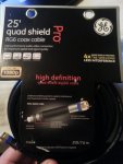
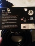
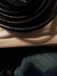
GE quad shield pro RG6 75 ohm coax cable. I got 25' at Walmart for $18. RadioShack had their own brand for $25. I didn't even bother looking at the packaging or anything at RS- I knew it would be cheaper at Walmart and for something better quality like the quad shield and gold connector pieces. Here are some pics:
 

Attachments

  • 20151214_173710.jpg
    20151214_173710.jpg
    51.3 KB · Views: 719
  • 20151214_173723.jpg
    20151214_173723.jpg
    48.4 KB · Views: 684
  • 20151214_173655.jpg
    20151214_173655.jpg
    38.4 KB · Views: 692
Last edited:

lio_n63

Member
Premium Subscriber
Joined
Jun 18, 2013
Messages
61
Location
Central New Jersey, USA
Hmm, I guess I missed that fact, thanks.
That means I can use my Dad's 75ohm quad coax RG6 spools, he has 2 huge spools sitting in the garage :) Just need to buy crimp tools for RG6 to BNC.

Just get a BNC male to coax female adapter. That's what I did. I got that at radioshack along with the 75-300 ohm balun. I've been told by a radioshack worker that the gold connector/adapter piece is best to help prevent any interference/signal loss (he's known at the store to be an expert when it comes to scanning and the related things). The thing is that so many RSs closed down, hopefully you have one nearby that sells these. If not you could probably get them off of amazon.

Balun: https://www.radioshack.com/products/indoor-outdoor-matching-transformer?variant=5717015365

Coax to BNC adpter: https://www.radioshack.com/products/gold-plated-f-connector?variant=5717650949

My question for this balun is- if the coax part of it is being supplied with the the 75 ohm coax cable, then what gives the other side, the end terminals of the balun, the 300 ohm supply?
 
Last edited:

majoco

Stirrer
Joined
Dec 25, 2008
Messages
4,315
Location
New Zealand
I don't know if the "High Definition Digital Cable" works with "High Frequency Analogue Radio Signals".... :)
 

popnokick

Member
Premium Subscriber
Joined
Mar 21, 2004
Messages
2,868
Location
Northeast PA
By design, the feed point of the VHF/UHF OCFD all-band scanner antenna is 300 ohms. The TV transformer balun provides the match to the 75 ohm coax, and some isolation.
 

kandrey89

Member
Feed Provider
Joined
Dec 11, 2009
Messages
320
Location
San Ramon, CA USA
By design, the feed point of the VHF/UHF OCFD all-band scanner antenna is 300 ohms. The TV transformer balun provides the match to the 75 ohm coax, and some isolation.
Uhmm, I've read that it varies from 200ohm to 300ohm design to design, but I'm not exactly sure what determines antenna impedance.

And it's not a 300ohm supply, it's the antenna intrinsic impedance, and it's called Balanced because the current flowing through the antenna is the same between input and output, where as the scanner is Unbalanced because the ground is at a fixed potential, and the input sinks all the current through a resistor.
 

lio_n63

Member
Premium Subscriber
Joined
Jun 18, 2013
Messages
61
Location
Central New Jersey, USA
majoco- It's still rg-6 coax cable so it should still work anyways, shouldn't it? The only reasons I got that one was because it has the gold ends and extra shielding from the quad shield which all help to reduce interference and thus reduced signal loss. The high definition part is, I assume, because of the gold ends and quad shield and, for usage for display purposes, will give a better flow quality to the video display signal causing high definition picture on a TV screen. Because it's being used in a scanner antenna setting, those extra qualities should give better, for lack of a better word, definition to the quality of signal being produced in this case for frequencies through the scanner in a similar way that it would be doing for a TV display. So in a nutshell, whatever is making the TV display HD is the same thing that would produce a better and less interfered-with signal, right? That's just kind of what I assumed after seeing the "High Definition Digital Cable" and the 1080p, etc when I bought it. Like I said previously, I'm no expert with this stuff, but that does seem to make sense. :D
 
Last edited:

HelixArray

Member
Joined
Jul 24, 2007
Messages
100
Location
TN
Hmm, I guess I missed that fact, thanks.
That means I can use my Dad's 75ohm quad coax RG6 spools, he has 2 huge spools sitting in the garage :) Just need to buy crimp tools for RG6 to BNC.
From amazon I bought a Etekcity multifunctional coax compression tool($18) and a coaxial stripper($5)for convenience to say the least. I almost sliced my thumb open when stripping coax with a razorblade and then some braid pierced under my fingernail. Who knew coax could be so dangerous. My stripper is still in the mail from China, they must be using a row boat for delivery.


Here's how I did my T-fitting -> Imgur photo of T-fitting:
I used Devcon 31345 2 Ton clear epoxy to secure the copper to plastic and ontop of the baluns screws. Probably should've checked to make sure the transformer was good before I did that though.

I'm making one out of some cheaper metal just to compare against the copper one at same height, same coax and same model balun. I need 3 more of these for my hand held and dongles. Trying out the wire version when my balun arrives.
 

HelixArray

Member
Joined
Jul 24, 2007
Messages
100
Location
TN
^ yeah, 3/4" copper pipe with a 3/4" CPVC fitting per wiki... I dry fit the stuff at lowes. I only used the epoxy because I wanted the pipes straight, without the epoxy the fit was snug but could be moved out of alignment. Plus, one of my screw holes started stripping.
 

lio_n63

Member
Premium Subscriber
Joined
Jun 18, 2013
Messages
61
Location
Central New Jersey, USA
^ yeah, 3/4" copper pipe with a 3/4" CPVC fitting per wiki... I dry fit the stuff at lowes. I only used the epoxy because I wanted the pipes straight, without the epoxy the fit was snug but could be moved out of alignment. Plus, one of my screw holes started stripping.

What's dry fitting? Sorry, kind of new to this stuff... And the epoxy won't affect the signal or how well it works? Do you think that screwing in on both sides of the tee would hold it in better without putting too much weight on one screw to hold it in place causing it to strip? Or will a screw on both sides mess with the signal also....
 

wbswetnam

Member
Premium Subscriber
Joined
Oct 11, 2005
Messages
1,808
Location
DMR-istan
From amazon I bought a Etekcity multifunctional coax compression tool($18) and a coaxial stripper($5)for convenience to say the least. I almost sliced my thumb open when stripping coax with a razorblade and then some braid pierced under my fingernail. Who knew coax could be so dangerous. My stripper is still in the mail from China, they must be using a row boat for delivery.

I have a coax stripper that I bought from Radio Shack a few years ago but but I was dissatisfied with it. I use a box cutter and a wire stripper these days to prep the coax for attaching a plug. I've put so many plugs on coax I guess I've got a method down now.
 

HelixArray

Member
Joined
Jul 24, 2007
Messages
100
Location
TN
^ Yeah, I thought I needed one to be able to use the compression connectors, but it turns out I pretty much had the BNC type on almost all the way by hand. The first time I compressed the F-type for my Gray-Hoverman antenna, I over compressed it and shattered the plastic. The plastic about caught me in the eye. My fault, as I'm always rushing things I guess.


@ lion
Dry fit, I guess, is a plumbers term for making sure all pipes, T's, elbows, etc.. fit before affixing them permanently.

For the record. I have to say that this model of antenna fits my over-all scanning needs perfectly. 9 stars out of 10 .
Easy, fun and depending on materiel, affordable to make. The last antenna I made in 2004 was this abortion of a WIFI antenna made from a pringles can that went terribly wrong. :)
 
Last edited:

lio_n63

Member
Premium Subscriber
Joined
Jun 18, 2013
Messages
61
Location
Central New Jersey, USA
@ lion
Dry fit, I guess, is a plumbers term for making sure all pipes, T's, elbows, etc.. fit before affixing them permanently.

For the record. I have to say that this model of antenna fits my over-all scanning needs perfectly. 9 stars out of 10 .
Easy, fun and depending on materiel, affordable to make.

Very glad to hear another great review about the OCFD-it kind of keeps me motivated to actually go through with building it. I'll probably end up building mine closer towards the weekend and I really hope it brings in a much better signal than my diamond rh77ca (not to say that the diamond sucks, it's actually quite a good antenna, but there is definitely a good deal of room for improvement).

The last antenna I made in 2004 was this abortion of a WIFI antenna made from a pringles can that went terribly wrong. :)

LOL- pringles can......gotta love it... :D
 
Status
Not open for further replies.
Top