Thought I would chime in on the firecracker.Also the firecracker isn’t what people think it is. It’s pretty much just a housing for a very flimsy element inside - not as awesome or super as people think they are/were - and why the Sinclair gained popularity.
if you crack one open you’ll see it’s just some wire. One of the reasons why Motorola incorporated a SWR sensor into their radios (will display “bad antenna” on the display in a high SWR/short condition).
I am posting this information about my interest regarding this very popular North American VHF railroad antenna as there seems to be some incorrect information on this and other sites regarding it. To clear the air...
The ASP-16's predecessor was, as far back as I can ascertain, a Farnsworth Radio Laboratories model M500-2. The antennas patent was submitted April 28th, 1947 by Robert G. Schriefer of the Farnsworth Research Corporation of Indiana, and granted November 28th, 1950, number 2,531,476 as an "Ultra-high frequency antenna". Here is one in my collection with before/after restoration. It is unique in the fact that there are two dissimiliar metals that make up the antenna. The inner support and outer can is steel, however the foot is brass.


Today's version of the ASP-16 antenna is an omnidirectional, 50 Ohm, all brass, rugged, single band, non-tunable type with a nominal frequency bandwidth of 4 MHz between 158-162 MHz when properly attached to a surface that will provide an acceptable ground plane. Overall length excluding SO-239 is 11 3/8" with a weight of 4lbs 4 oz and a listed power capability of 100 Watts.


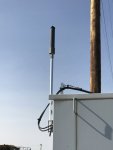
The antenna is comprised of a SO-239 UHF connector on the center bottom of a circular mounting foot that has four holes to mount to a locomotive or railcar. The foot is 2 13/16" in diameter which is welded (brazed) to a 1" diameter brass pipe that extends from the mounting foot approximately 11" to a brass disk. This brass disk (looks as if it) is welded to a 3" diameter, 1/8" thick cylinder that is 8" long that surrounds the supporting 1" pipe and makes up the most visible part of the antenna.
The center conductor of the coax enters the antenna via an SO-239 in the mounting foot and is brought up through the 1" pipe via a silver wire to a wide nut encapsulated in plastic. The energy is then sent through the 1" pipe via holes to the outside 3" cylinder via silver all thread that is electrically coupled to it via star lock washers held in place by ny-lock nuts. From here the electrical path takes the energy up to the top disk of the antenna where the center supporting pipe will take it all the way to ground via the supporting foot and the ground of the SO-239.


The antenna really isn't as flimsy as some would say. In my personal experience with this antenna I have found it to have just as good of radiation qualities of a quarterwave whip. Other than having a higher profile over the Sinclair Excaliber antennas which make it a bit more susecptable to damage the engineering and construction that goes into this antenna is one of the reasons it is quite robust - making it a little more expensive.
You can see the same photos at: Firecracker Photos
")