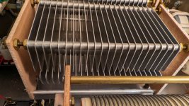
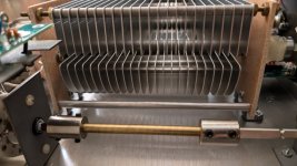
I have a second hand Palstar AT2K that I purchased some months back. I just replaced two broken couplers that were tied to the Input and Output dials and their respective tuning capacitors.
If someone owns one of these could you pop the hood and take a picture of the position of the tuning capacitor elements when both are set to zero? I currently set it so the fixed element and the moving element have the flat edges aligned in parallel horizontally when set to zero. However I don't know if this is correct since It was broken when I bought it.
I was doing some SWR scans with my mini 1300 and I can tune things perfectly, however the dials are way off from the examples in the manual to use as starting points.
Attachments
Last edited:


