prcguy's mast mount filter/preamp/diplexer thingee

Status
Not open for further replies.

Ubbe

Member
Joined
Sep 8, 2006
Messages
9,541
Location
Stockholm, Sweden
The way I checked the whole chain from antenna and down where to measure the signal strenght from a couple of other towers, that I also managed, when the site where first installed and then keep a record of all values of the site each time a site check where done. That way I could also see if the signal dropped from one of the other towers, that could then have a possible bad antenna radiation, if its power amplifier where still good and there wasn't a new high rise building blocking the signal.

/Ubbe
 

prcguy

Member
Premium Subscriber
Joined
Jun 30, 2006
Messages
16,048
Location
So Cal - Richardson, TX - Tewksbury, MA
I don't believe a broad band preamp with 1dB compression point like the $30 PGA103+ when connected to a broad band antenna like a Discone will work in any major city without some narrow band pass filtering. It will start creating IMD with just a few moderate level signals and in reality it will get hit with hundreds of signals that will create lots of IMD. You may not even know its happening as the IMD will masquerade as an annoying high noise floor.

Years ago I had to design and build a 32 channel or "transponder" simulator for testing satellite receivers. It generated 32 QPSK and 8PSK modulated signals across the 250 to 2150MHz range and I got to do a lot of testing with it using anywhere from one to 32 carries simultaneously at various output levels. I used three different high level output amplifiers to try and avoid creating IMD with each amplifier sharing part of the output load but in the end it did create IMD when the output levels were near the maximum levels this device was intended to supply. It was interesting the IMD showed up as a very broad band noise floor and you could not pick out any single specific IMD signal. You would reach a certain output level and the noise floor of of each amplifier would start to rise and for every one dB you increased the input to the output amps, the noise floor or IMD would increase by 2dB. That is classic IMD at work.

The exact same thing will happen with a preamp that only has a 1dB compression point, or IP1 rating of 0dBm. You might think or hope its helping reception but in fact its messing it up by creating lots of ghost signals or IMD inside the amplifier because its just not up to the task. It might work ok on a remote island somewhere with no transmitters on the island, or it might work just fine if you have a sharp skirted filter for a narrow frequency range, but not connected to a broad band antenna. You need a much higher IP1 than 0dBm!

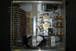
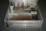
Here is a pic of the satellite spectrum simulator I built mostly in my garage that has a small fortune in MiniCircuits parts inside. It was a very valuable experience for me as I was able to experiment with creating and measuring IMD under very controlled conditions. Even though it did create some IMD with its intended purpose for my company, it was a great success.
simulator.JPG


Top view.JPG

But keep in mind that it has a 3.5dB noise figure. The 1dB compression point are at +20dBm input. A $30 PGA103+ based amplifier has its 1dB compression point at 0dBm input but have instead a much better 0.5dB noise figure. If you have antenna signals that are less than 0dBm you would grab signals 3dB lower down in the noise with the PGA103+ and also save a lot of money. The high level amp are intended for extreme situations.

/Ubbe
 
Last edited:

Ubbe

Member
Joined
Sep 8, 2006
Messages
9,541
Location
Stockholm, Sweden
I've tried pga103+ at "RF hell" with at least 20 transmitters at the neigbouring buildings roof and no problem using it without any filters. Only the receivers used gets overloaded if the output are not attenuated to a level where the receivers can handle it, different levels for different quality of receivers and all got improved reception compared to using them without the amplifier.

Easiest way to check for correct input level to a receiver are to use a variable attenuator and listen to a weak signal, if you have a signal generator you can insert a weak signal before the amplifier using a 30-40dB tap, and adjust attenuation to maximum signal quality in the receiver. Often a FM trap filter will allow a higher signal level and filtering out other sources like cellular and pager signals will also improve the signal level and the quality of reception. I know several people who use pga103+ and so far it's never been any problems in the actual amplifier. I regard it as being one of the amplifiers with the best cost/performance ratios. Of course extreme situations will require extreme solutions.

/Ubbe
 

prcguy

Member
Premium Subscriber
Joined
Jun 30, 2006
Messages
16,048
Location
So Cal - Richardson, TX - Tewksbury, MA
I looked up the specs on a PGA103+ and its 1dB compression is not 0dBm but 22.5dBm with an IP3 of 45dBm. That's why you are able to use it with a broad band antenna. There are still many cities where that will not work without creating lots of IMD problems.

I've tried pga103+ at "RF hell" with at least 20 transmitters at the neigbouring buildings roof and no problem using it without any filters. Only the receivers used gets overloaded if the output are not attenuated to a level where the receivers can handle it, different levels for different quality of receivers and all got improved reception compared to using them without the amplifier.

Easiest way to check for correct input level to a receiver are to use a variable attenuator and listen to a weak signal, if you have a signal generator you can insert a weak signal before the amplifier using a 30-40dB tap, and adjust attenuation to maximum signal quality in the receiver. Often a FM trap filter will allow a higher signal level and filtering out other sources like cellular and pager signals will also improve the signal level and the quality of reception. I know several people who use pga103+ and so far it's never been any problems in the actual amplifier. I regard it as being one of the amplifiers with the best cost/performance ratios. Of course extreme situations will require extreme solutions.

/Ubbe
 

Ubbe

Member
Joined
Sep 8, 2006
Messages
9,541
Location
Stockholm, Sweden
I looked up the specs on a PGA103+ and its 1dB compression is not 0dBm but 22.5dBm with an IP3 of 45dBm.
At the output, yes. Which equals to 0dBm and +20dBm at the input which few people will encounter. You have to sit very close to a transmitter site to overload a pga103+ based amplifier.


If a site are allowed to transmit 100watt, 50dBm, and at 800Mhz the signal loss in air are 90dBm at 1/2 mile, 100dBm at 2 miles, and 110dBm at 5 miles, the resulting receive signal level will be less than -40dBm with a zero gain antenna.

/Ubbe
 

prcguy

Member
Premium Subscriber
Joined
Jun 30, 2006
Messages
16,048
Location
So Cal - Richardson, TX - Tewksbury, MA
Not looking to pick on you but the free space loss is not in dBm, its simply dB.

Using your example at 1/2 mile and a signal of -40dBm hitting the preamp, if you have two signals that high the PGA103+ will create some serious IMD. IMD does not happen at the 1dB compression point, it starts happening 50dB or 60dB or more lower than that. Even at 5 miles, two resulting signals at -60dBm each will create measurable IMD in a PGA103+. That IMD from two signals may not fall on a frequency you scan but add a hundred of them and it will land on something you want to receive and it will degrade reception.

At the output, yes. Which equals to 0dBm and +20dBm at the input which few people will encounter. You have to sit very close to a transmitter site to overload a pga103+ based amplifier.


If a site are allowed to transmit 100watt, 50dBm, and at 800Mhz the signal loss in air are 90dBm at 1/2 mile, 100dBm at 2 miles, and 110dBm at 5 miles, the resulting receive signal level will be less than -40dBm with a zero gain antenna.

/Ubbe
 

RFI-EMI-GUY

Member
Joined
Dec 22, 2013
Messages
7,264
At the output, yes. Which equals to 0dBm and +20dBm at the input which few people will encounter. You have to sit very close to a transmitter site to overload a pga103+ based amplifier.


If a site are allowed to transmit 100watt, 50dBm, and at 800Mhz the signal loss in air are 90dBm at 1/2 mile, 100dBm at 2 miles, and 110dBm at 5 miles, the resulting receive signal level will be less than -40dBm with a zero gain antenna.

/Ubbe

The antenna farms can start to eat you because the power for each carrier is additive.

100 W 50 dBm transmitter
Combiner loss -3 dB
TX Line loss -2 dB
Antennna Gain +10 dB

Total +55 dBm

2nd transmitter +3 dB
Total =58 dBm
4th transmitter +3 db
Total =61 dBm
8th transmitter +3 dB
Total =64 dBm
16th transmitter +3db
Total =67 dBm
32nd transmitter +3 dB
Total = +70 dBm

Now add in an FM and/or TV broadcast station
 

Ubbe

Member
Joined
Sep 8, 2006
Messages
9,541
Location
Stockholm, Sweden
IMD does not happen at the 1dB compression point, it starts happening 50dB or 60dB or more lower than that.

IP3 are the theoretical point where the fundamental signal and the IMD components are at the same level. From there the IMD component drops three times faster in level than the fundamental frequency. If IP3 are at +40dBm then at +20dBm the IMD have dropped to -20dBm and at -0dBm its down to -120dBm, the squelch level of most receivers. If the gain where 20dB then the input are at a -20dBm level when the IMD's are at the -120dBm. I would expect all scanners to have worse figures than that.

A popular scanner like SDS100/200 have something like an IP3 of -14dBm in band and 0dBm out of band figure in its SDR receiver and use an additional inbuilt preamp to boost the poor sensitivity of the SDR receiver.

/Ubbe
 

prcguy

Member
Premium Subscriber
Joined
Jun 30, 2006
Messages
16,048
Location
So Cal - Richardson, TX - Tewksbury, MA
I believe there is a miscalculation somewhere. I think IMD will be produced at levels lower than you show and at levels that will be picked up by a receiver. If you have a spectrum analyzer available, take a snapshot every 10MHz or so across the VHF and UHF bands with an RBW narrow enough (like 10KHz) to show every carrier out there. You should see a hundred or more frequencies in use at any given time during the day and where I live its many hundreds. You should also see some levels that easily reach -20dBm or more. That is a recipe for IMD in a low IP1/IP3 broad band preamp with no front end filtering.

Even though some scanners have really bad IP3 ratings, they do have band pass filtering that helps them survive in big cities. In RF Hell Los Angeles, CA my little Whistler TRX-1 and older GRE scanners play nice with outside antennas and don't seem to have any IMD or overload problems. That is a miracle right there.

IP3 are the theoretical point where the fundamental signal and the IMD components are at the same level. From there the IMD component drops three times faster in level than the fundamental frequency. If IP3 are at +40dBm then at +20dBm the IMD have dropped to -20dBm and at -0dBm its down to -120dBm, the squelch level of most receivers. If the gain where 20dB then the input are at a -20dBm level when the IMD's are at the -120dBm. I would expect all scanners to have worse figures than that.

A popular scanner like SDS100/200 have something like an IP3 of -14dBm in band and 0dBm out of band figure in its SDR receiver and use an additional inbuilt preamp to boost the poor sensitivity of the SDR receiver.

/Ubbe
 

Ubbe

Member
Joined
Sep 8, 2006
Messages
9,541
Location
Stockholm, Sweden
Calculations are for only one additional carrier that creates IMD. As RFI-EMI-GUY points out each additional carrier probably adds a wide spectrum spread problem.

To get -20dBm levels you probably have to be within 100 yards from a site, or 400 yards if you use a 12dB gain antenna, or 5 miles from a 25KW FM broadcast transmitter.

It's not much filtering going on in a standard scanner like the TRX. One filter covers the 405-660MHz range and one filter for the 660-1300MHz. They open up the whole frequency band to the receiver.

/Ubbe
 

prcguy

Member
Premium Subscriber
Joined
Jun 30, 2006
Messages
16,048
Location
So Cal - Richardson, TX - Tewksbury, MA
How many people in the average city live within 5 miles of an FM broadcast transmitter? I think many. If they are within 5 miles of one then they are probably close to several and to a number of high power TV transmitters and paging transmitters and cell phone towers and so on. It all adds up quickly.

Calculations are for only one additional carrier that creates IMD. As RFI-EMI-GUY points out each additional carrier probably adds a wide spectrum spread problem.

To get -20dBm levels you probably have to be within 100 yards from a site, or 400 yards if you use a 12dB gain antenna, or 5 miles from a 25KW FM broadcast transmitter.

It's not much filtering going on in a standard scanner like the TRX. One filter covers the 405-660MHz range and one filter for the 660-1300MHz. They open up the whole frequency band to the receiver.

/Ubbe
 

prcguy

Member
Premium Subscriber
Joined
Jun 30, 2006
Messages
16,048
Location
So Cal - Richardson, TX - Tewksbury, MA
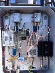
Another slight upgrade to my tower top filter/preamp today. I received an HP/Agilent RF Limiter that will take up to 10 watt input with low loss through 1.8GHz and clamp that to no more than around 10dBm or 10 miliwatts. I installed this at the input of the 118 to 512MHz amplifier to protect it from possible damaging overload from other equipment here.

I have a 2m and 70cm repeater feeding Yagi antennas on the same tower for local coverage and if I accidentally turn the antennas the wrong way the Yagi's would be pointing right into my low freq Discone about 6ft away. At the power levels the repeaters are operating at there could be several watts hitting the input of the low frequency amplifier. Now the amplifier will never see input power beyond its design ratings.

The tiny new limiter is in the lower right of the picture below screwed onto the amplifier. I got the limiter for $27 off Ebay and these are many hundreds of $$ new.

tower amp.JPG
 

vagrant

ker-muhj-uhn
Premium Subscriber
Joined
Nov 19, 2005
Messages
3,337
Location
California
Thanks for that. I nabbed the last one at the $27 price. There is another seller that has them for $30 +$12 shipping.

I found additional 5086-7283 models on eBay, but they are copper in color and from China / Hong Kong.
 

vagrant

ker-muhj-uhn
Premium Subscriber
Joined
Nov 19, 2005
Messages
3,337
Location
California
I have a request. Please label the parts using that last photo with 1, 2, 3, or similar and identify them with their model number and what they are, filter, amp, etc. Some are clear and obvious, others not so much. Labeling the exterior ports with the connected antenna range would also be helpful.

Also, is this going to multiple receivers, or all to the R8600? If multiple receivers, what exactly are you using to distribute the signal?

Thank you very much
 

prcguy

Member
Premium Subscriber
Joined
Jun 30, 2006
Messages
16,048
Location
So Cal - Richardson, TX - Tewksbury, MA
I can mark up a picture and make a schematic but it might take awhile to do that. What freq range are you interested in? This exact setup would be difficult to duplicate as some components are not readily available like the military surplus diplexer.

If you only need 118 to 1,000Mhz or so I would consider a low and high range Discone or a low range Discone and gain type 700MHz-1GHz antenna, then the nice diplexer I had originally which had an 80-512MHz and 698-2700MHz split. Connect both antennas directly to that and a MiniCircuits ZBSF-95-N FM trap then to an RF limiter if needed, then a single MiniCircuits ZFL-1010 amplifier. You could also use a 12V transfer relay to bypass the amp for straight through operation when power is removed.

In this case the antennas are combined onto one coax with a diplexer and one amplifier is used for the entire range, which is about 50MHz to 1GHz. I would consider a 30MHz high pass filter in front of the amp if you do high power HF at the same site.

Right now the output of my power inserter goes to a MiniCircuits ZAPD-30 2-way divider that covers 20MHz to 3GHz and to my Icom R8600 and R7100. I have a four way divider with similar specs if I need to feed more receivers.


I have a request. Please label the parts using that last photo with 1, 2, 3, or similar and identify them with their model number and what they are, filter, amp, etc. Some are clear and obvious, others not so much. Labeling the exterior ports with the connected antenna range would also be helpful.

Also, is this going to multiple receivers, or all to the R8600? If multiple receivers, what exactly are you using to distribute the signal?

Thank you very much
 

vagrant

ker-muhj-uhn
Premium Subscriber
Joined
Nov 19, 2005
Messages
3,337
Location
California
A full schematic is not really needed and thank you for the reply with details. Still, I am just unsure of some of the filters.

What I would like to know is:
- The Mfg. and model of those 12v transfer relays ( I TX nearby as well and would want to shunt things a bit with a power switch. )
- The various Mfg./models of what appear to be barrel shaped filters. (When I look up the specs on the model # I will know where they go.)
- Even that Mini Circuit barrel filter is not that clear to read. (The Mini Circuit FM filter and amps are clear or you noted as much.)
- What model # is that diplexer? ( As you noted, I will probably need to find something available vs. the unicorn.)
- Whatever the squared corner item is in the bottom left taking in the feeds when it appears the relays are off.

* Thanks for the reminder about the 30 MHz HPF. I will definitely need that.
 

prcguy

Member
Premium Subscriber
Joined
Jun 30, 2006
Messages
16,048
Location
So Cal - Richardson, TX - Tewksbury, MA
The low pass filters are MiniCircuits SLP-550. The high pass filters are MiniCircuits SHP-800. A low pass filter is in front of the low freq amp and a high pass filter is in front of the high freq amp. These filters show up on Ebay in the $15-$20 range.

I also used the same filters with an SMA T adapter to make a diplexer. Its not perfect but since its after the preamps its not so critical. The best diplexer I've found is a Microlab BK-24N, but they are expensive new and rarely show up on Ebay cheap, but I did get mine for around $150. That diplexer is good to about 2.7GHz on the high pass and if you only need to go up to about 1GHz there are some on Ebay now that are just as good. The FM trap filter is the best I've seen so far and its a MiniCircuits ZBSF-95-N.

The coax relays are generic 12V transfer relays good to about 18GHz, so they are very low loss. I think they ran me about $15 ea used on Ebay. I'll try and find an Ebay listing for something similar. The last thing in the lower right of the picture is the Bias Tee and I think I posted info on that earlier in this thread. These handle at least 2A of current and its needed when all the relays and amps are powered up. They are also an Ebay item but from China, otherwise they would cost a few hundred $$.

A full schematic is not really needed and thank you for the reply with details. Still, I am just unsure of some of the filters.

What I would like to know is:
- The Mfg. and model of those 12v transfer relays ( I TX nearby as well and would want to shunt things a bit with a power switch. )
- The various Mfg./models of what appear to be barrel shaped filters. (When I look up the specs on the model # I will know where they go.)
- Even that Mini Circuit barrel filter is not that clear to read. (The Mini Circuit FM filter and amps are clear or you noted as much.)
- What model # is that diplexer? ( As you noted, I will probably need to find something available vs. the unicorn.)
- Whatever the squared corner item is in the bottom left taking in the feeds when it appears the relays are off.

* Thanks for the reminder about the 30 MHz HPF. I will definitely need that.
 
Status
Not open for further replies.
Top