I looked but couldn't find it. I found their site but couldn't find where to look at that issue...
let's see if I can cut & paste the text here:
A Better Battery Charger
When I first got interested in ham radio, the primary and most prevalent rechargeable battery type was the NiCAD. It was a wonder of modern technology: no longer did we have to waste money on non-rechargeables, or rely on a car battery when going portable.
Unfortunately this technology came with a down side: if not discharged properly before recharging, the battery would, over multiple repeats of this technique, develop a memory. This means that once a voltage level (let’s say ½ of the battery voltage) was established as the minimum to which the battery was discharged before a re-charge, then the battery no longer wanted to discharge below that level without some intensive care (and, in serious cases, that intensive care wouldn’t help either).
At this point I’d like to pause and explain the term “proper discharge”. This does
not mean zero volts. If a battery
were discharged to 0V, another potential problem could arise: the battery changes polarity. A bit of research into the specifications provided by various battery manufacturers indicate that 1/3 of the battery’s rated voltage is considered to be the “complete discharge” level. This 1/3 voltage level is just “a rule of thumb”; the purist might want to check the specification of their battery from the manufacturers’ or suppliers’ web site. (Also, a search on Wikipedia indicates that the minimum battery voltage before recharging is calculated by 0.90 x (# of cells / 2); another good source for determining that level is the battery manufacturer and/or the data sheet that comes with the battery.)
Now that we’ve established how far to discharge a battery and have gotten to the point of needing to recharge it, the question comes up: how
fast should it get charged? There are two considerations: a standard charge rate, and rapid charge. Rapid charge was a big selling point at one time for those people who were impatient (or didn’t have enough spare replacement battery packs available for more intense operation, like field day, hamfests, etc.). When I owned Icom H.T.s (Handheld Transceivers) of the IC-2AT and IC-3AT vintage, it was only their larger capacity batteries that had this option—because of their (albeit slightly) larger physical size, they were better able to handle the heat dissipation required during faster charging cycles. Even under those conditions I was told that the life expectancy of rapid charged batteries was reduced since the chemicals that the batteries were manufactured with would “cook” off due to the generated heat. This makes sense, since upon closer inspection I’ve often seen on individual cells that there’s a small pin-hole on one end that acts as a vent (this can be hidden a bit by the wrapping of heat shrink or similar material in battery packs, especially by battery packs having a slower charge rate like those used on cellular or cordless ‘phones, scanner radios, and so on). So—if we chose the rapid charge approach—what value (charge rate) do we chose? The charge rate depends on:
- Cell size—larger cell sizes can more readily dissipate the heat involved, and;
- The number of cells that are being charged. Assuming perfect conditions (all cells charging at the same rate), total charge current equals the maximum charge rate of one cell multiplied by the number of cells in the pack.
For safety, it’s important to follow the recommendations of whoever assembled the pack—either the manufacturer of the radio that the pack came with, or after-market battery supplier (in those cases where we’re making custom battery pack for a project, or having a battery pack re-built by a battery store to replace a battery pack that’s gone bad). Since rapid charging can be dangerous—causing everything from battery leakage, fire, to exploding batteries—this is definitely a situation where I try to err on the side of caution by doing extra checking of the manufacturers’ or suppliers’ recommendations before rapid charging of the battery pack, or (if the charging system has the option to let the user switch between modes) I select the standard charge rate.
So what is the standard charge rate? Again, the safest approach is to go directly to the manufacturers’ data or specification sheet, since they’re the ones with the research laboratory where experienced personnel have done all the design and testing. As a secondary bit of information, the following is from Wikipedia: “typically 1/10 of the ampere-hour rating of the battery” is a charge rate recommended there. Since this article is intended to apply to a variety of different battery types and sizes, the current limiting resistor used for battery charging has no specified value in the schematic; it needs to be determined by the user as it pertains to the particular battery pack being charged in your hamshack. (In the case of different packs needing to be charged, a simple rotary wafer switch can be used to select different resistor values as required by the various batteries being charged—just make sure you select the correct resistor
before you plug in the battery!)
So far I’ve used NiCAD batteries in my examples, so let’s take a look at other battery types. I’ll limit this to nickel metal hydride (NiMH) batteries, since that’s the only other type of battery technology I see in predominant use. (Yes, I know there are people out there who use lead-acid or gel cell batteries, but use of those aren’t as common.) From what I’ve been able to find out both by word-of-mouth and actual information on the Internet (primarily Wikipedia), actual operation is very similar to NiCAD batteries. Yes, this battery type (NiMH) is still susceptible to developing a memory although the situation does not seem as serious (i.e. it doesn’t seem to happen as readily) as with their NiCAD counterparts. To save both the actual batteries as well as replacement costs, I treat my NiMH batteries with the same care as their NiCAD counterparts.
To make certain that a battery would get recharged at the appropriate discharge level I wanted to build some type of circuit that would detect the charge level of a battery and switch on the charger at the appropriate time. This level detect also had to be variable so that I could set it to conform to whatever battery I wanted to watch, allowing me to use one charge detector for all my batteries, instead of multiple detectors with a fixed detection point for all of the different battery operated devices in the hamshack.
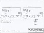
Since I was already building one such detector—for the low voltage detect—it didn’t take much more effort to build a second such detector which would sense maximum charge level to turn the charger off when the battery was full, to avoid potential damage caused by over-charging a battery. This lead to the circuit shown in schematic #1, a window detector (For those of you familiar with hysteresis curves, the window detector is simply a device that has variable trigger points along the hysteresis curves). Pin 3 on U1 and pin 2 on U2 sense the voltage level of the battery being charged, and trigger the operational amplifiers (op-amps) accordingly; the higher the voltage across the battery, the closer it is to being fully charged. The battery is charged through Rlimit as we discussed earlier in the text. Relay “RLY 1” toggles on and off based on the maximum voltage determined by the setting of potentiometer P1, and minimum voltage of potentiometer P2.
One of the challenges that came up during the design was the minimum voltage put out for the low (or “0”) signal of the op-amps: unlike digital integrated circuits, analog I.C.s don’t always go to 0 volts on logic low or all the way up to +V when fully conducting. While this may be good in analog circuits to avoid signals clipping at either extreme, this is not good for digital signals: digital circuits require a more definite logic “0” or “1”.
To solve this problem, I used a Schmidt Trigger, in the form of an inverter I.C., MC14584 (or simply “4584”, depending upon the manufacturer that you find). Since this inverted the logic signal, and since there are six devices per fourteen pin package, there were enough such circuits left over to be able to place two in series for the desired logic level (one could also have simply used the normally open, instead of the normally closed connections on the relay—builders’ choice!). As always, never leave unused inputs floating—tie them to either ground or +V.
Components chosen for this circuit are not critical, with only minor considerations as follows:
- Rlimit must be of a power rating suitable for the charge current required by the battery;
- D1 & D2 are for signals only (to turn on Q1)—the more expensive power diodes are over-kill;
- Q1 needs to be able to handle whatever power level required by the relay. If your application requires a relay with high(-er) contact current ratings because you’re charging a bigger battery, consider using a small relay for RLY1 that can be driven by whatever transistor you have available in your parts bins, and use the smaller relay to toggle a bigger relay (again, parts available in your test bench can be used—nothing special is needed here);
- D3 needs to handle the reverse EMF created by RLY1 when it opens so that Q1 does not get destroyed or damaged by the voltage spike. I used a 1N4001 rectifier diode because I had a few left over from a power supply project, but anything similar will do;
- P1 & P2 are not critical as long as the values are not so low as to cause device failure level currents to flow through either, since they are connected across the power supply.
There are a few design considerations that went into developing this circuit, which might help in determining your build of this circuit:
- To keep accessibility of parts easy (both for duplicating this circuit as well as the need for eventual, potential repairs), the circuit was designed to use commonly available parts;
- Twelve volts to power this circuit was chosen to make it easy to power it from voltages commonly found in the hamshack, but if different voltages are needed for your battery, the 741 op-amp I.C. can operate from a split supply of + 18V (double-check the data sheet of whatever op-amp you decide to use to play it safe), so there is a bit of “wiggle room” to customize this circuit to suit the users’ needs;
- Since we’re not dealing with high voltages or high-impedance circuits susceptible to stray RF, the type of enclosure for this circuit is not critical (plastic will do) unless you’re operating near a QRO station where the RF may affect the op-amp operation (my personal preference is a shielded, metal box that’s grounded as S.O.P.).
- Although the battery chargers I’ve seen do not have a fuse between the battery and charger, it might be worth considering especially if we’re dealing with higher current devices that could melt the hook-up wiring.
Setting up the circuit
Before charging my first battery I went through the following set-up and test:
- I substituted the battery with Px;
- Using a voltmeter, I alternately checked both the wiper arm of P1 and P2, turning each to the required voltage (i.e. fully charged voltage in the case of P1, and discharged voltage as controlled by P2);
- I varied Px while measuring the voltage on the R1/U3B junction to make certain that the circuit switched properly as designed. (I did this to make sure the circuit works as designed; it’s also an easy check for the builder to make sure everything got wired up correctly.)
In Conclusion
The final construction—i.e. things like the enclosure, connections to the battery, and status L.E.D.s—have intentionally not been discussed not only to avoid “information over-load” by the reader caused by a cluttered schematic but also because these items are determined by the needs of the specific batteries being used in the readers’ hamshack, and the builders’ preferences (for example not everyone wants status lights blinking at them!). Regardless of the readers’ specific needs, I hope this circuit will fill a gap left by existing battery chargers.
Yup-guess it fit; picture of schematic's attached...

 OMG people! Are you kidding????? There are batteries, chargers, expensive equipment, but mostly personal preferences.... Just look at this post and remind yourselves in the scheme of things that batteries, chargers, equipment, and hardware suggestions/instructions are personal preferences..... Those who 'shout' the loudest are usually supposed 'experts'(?), think about it.