Do you have underground utilities or aerial? Could be corrosion/oxidation on fuses or surge protection devices on the power lines if aerial. I had nasty interference on VHF all over a coastal town due to that. I actually got the power company to clean it all up.Then is must really be bad, I was still receiving it almost 2 miles away in the car.

-
To anyone looking to acquire commercial radio programming software:
Please do not make requests for copies of radio programming software which is sold (or was sold) by the manufacturer for any monetary value. All requests will be deleted and a forum infraction issued. Making a request such as this is attempting to engage in software piracy and this forum cannot be involved or associated with this activity. The same goes for any private transaction via Private Message. Even if you attempt to engage in this activity in PM's we will still enforce the forum rules. Your PM's are not private and the administration has the right to read them if there's a hint to criminal activity.
If you are having trouble legally obtaining software please state so. We do not want any hurt feelings when your vague post is mistaken for a free request. It is YOUR responsibility to properly word your request.
To obtain Motorola software see the Sticky in the Motorola forum.
The various other vendors often permit their dealers to sell the software online (i.e., Kenwood). Please use Google or some other search engine to find a dealer that sells the software. Typically each series or individual radio requires its own software package. Often the Kenwood software is less than $100 so don't be a cheapskate; just purchase it.
For M/A Com/Harris/GE, etc: there are two software packages that program all current and past radios. One package is for conventional programming and the other for trunked programming. The trunked package is in upwards of $2,500. The conventional package is more reasonable though is still several hundred dollars. The benefit is you do not need multiple versions for each radio (unlike Motorola).
This is a large and very visible forum. We cannot jeopardize the ability to provide the RadioReference services by allowing this activity to occur. Please respect this.
You are using an out of date browser. It may not display this or other websites correctly.
You should upgrade or use an alternative browser.
You should upgrade or use an alternative browser.
Specific interference on the VHF Business High band
- Thread starter videobruce
- Start date
- Status
- Not open for further replies.
Wherever this is coming from it's surely not here! I would of found it months ago!! I can drive 2 miles away and still pick it up using the same model scanner receiver in the car w/ a roof antenna.
The only thing I have a local problem with is my next door neighbors outdoor hot tub that generates broadband noise around 390MHz that almost wipes out operation of one of my garage door openers. The other opener operates at 314MHz and isn't affected.
The power utilities are aerial and the service was almost fully replaced (new poles & xformers) many years ago. We rarely have power failures unlike before that was due to a overloaded neighborhood feeders. Again, there is a substation near, but that isn't it.
I wonder if this new 5G cell service just above the cutdown UHF TV spectrum (above 600 MHz) would cause it?
I still wouldn’t rule out power line issues.Wherever this is coming from it's surely not here! I would of found it months ago!! I can drive 2 miles away and still pick it up using the same model scanner receiver in the car w/ a roof antenna.
The only thing I have a local problem with is my next door neighbors outdoor hot tub that generates broadband noise around 390MHz that almost wipes out operation of one of my garage door openers. The other opener operates at 314MHz and isn't affected.
The power utilities are aerial and the service was almost fully replaced (new poles & xformers) many years ago. We rarely have power failures unlike before that was due to a overloaded neighborhood feeders. Again, there is a substation near, but that isn't it.
I wonder if this new 5G cell service just above the cutdown UHF TV spectrum (above 600 MHz) would cause it?
I’d revisit the spectrum analyzer and adjust the gain, resolution and reference level to be able to see a several MHz wide chunk of spectrum with the bottom being less than -110 dBm at least if possible.
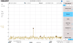
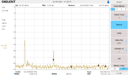
Taking a much closer look at this, I narrowed down the span to 500kHz + & - and tried to follow this interference. It runs around 20dB above the noise floor. No preamp in use, I have 2 FM broadcast stations 1 mile away (in opposite directions). It fluctuates in strength by around 5 dB and the drifting jumps back & forth.
For example;
For example;
Attachments
Sure sounds like a VOR (that sample was probably from an AM detector, not an FM discriminator).
One intermod possibility: 3 x FMBroadcast - VOR = VHF high
Nearby (10 km radius from centroid of Buffalo) high-power (> 40 kW ERP) FM broadcast include: 92.9 @ 76 kW, 93.7 @ 47, 96.1 @ 47, 103.3 @ 49, 104.1 @ 50, 106.5 @ 50
Nearby VORs include: 116.4 BUF, 111.0 IAG, 116.2 DKK, 108.2 GEE (more?)
There are certainly other mix possibilities that could include high-power VHF (maybe a trunking control channel)?
Or maybe one of the VORs has just gone squirrely all by itself.
mrsvensven
Member
- Joined
- Jul 27, 2006
- Messages
- 176
How far to the left and right does the signal move? If it moves over a swath of spectrum wider than a standard 12.5KHz channel, it's certainly interference and not a legitimate signal from any licensed user.Taking a much closer look at this, I narrowed down the span to 500kHz + & - and tried to follow this interference. It runs around 20dB above the noise floor. No preamp in use, I have 2 FM broadcast stations 1 mile away (in opposite directions). It fluctuates in strength by around 5 dB and the drifting jumps back & forth.
For example;
The fact that you can see it so cleanly on the spectrum analyzer means this should be relatively easy to track down. Go for a drive and see in what direction the signal gets stronger. You should be able to get within a block or two just by driving around and looking at signal strength. If you have a good directional antenna to see in what direction the signal is strongest, you might be able to track it faster and/or to a more precise location.
The recordings were FM mode. I did switch to AM and it was basically the same, but at a much lower audio level. I also tried WFM, but there was close to no audio heard.
160.80 seems the lowest it goes and 161.25 seems to be the highest. That screen save span was 1MHz total.
That Siglent SA is AC only. I do have a 'RF Explorer' that I could use, but I would want to limit it to it's own antenna due to overload caution warnings in their literature.
160.80 seems the lowest it goes and 161.25 seems to be the highest. That screen save span was 1MHz total.
That Siglent SA is AC only. I do have a 'RF Explorer' that I could use, but I would want to limit it to it's own antenna due to overload caution warnings in their literature.
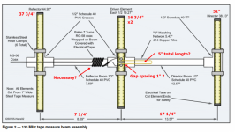
I want to build that 3 element Yagi tape measure antenna, but I don't know which calculator to use as far as the dimensions and spacing of the elements.
Here are some of the choices;
 www.steeman.org

 www.changpuak.ch
 3g-aerial.biz
The problem is some of these show the spacing the same between the 3 elements which I believe isn't correct. Also element diameter comes into play, but how does one determine that with a 'flat tape measure'??
Here are some of the choices;
Maple Leaf Communications - Antenna Calculator - 3-Element Yagi
Use our simple calculator to determine approximate dimensions of materials needed to build a 3-element Yagi/Uda antenna, and then shop for your needs on our other pages and select from our inventory of aluminum, fiberglass, coax, connectors, and other parts and accessories for amateur radio and...
www.mapleleafcom.com
Jeroen Steeman - Entrepreneur, engineer, software developer and wildlife enthusiast with a passion for technology.
Yagi Antenna Design Calculator - Calculate the dimensions required for a directional antenna for a specific frequency.
www.steeman.org
Yagi Uda Antenna (Rothammel)
Free Online Engineering Calculator to find the Dimensions of a yagi Uda Antenna for a given Frequency Range and Length.
Amateur Beam Antenna Calculator
This calculator is designed to give the critical information of a particular beam antenna.
www.csgnetwork.com
3-elemets Yagi-Uda online calculator - 3G-aerial
Optimized 3-el Yagi-Uda design with over 7.3 dB gain and 50 ohm input impedance - online calculator
The problem is some of these show the spacing the same between the 3 elements which I believe isn't correct. Also element diameter comes into play, but how does one determine that with a 'flat tape measure'??
Last edited:
Ubbe
Member
Distance between elements are different depending of bandwidth wanted versus the gain and impedance and direction pattern, so it could be the same distance between them. Diameter are the length along the radiowave and will fit the radiowave over a wider frequency range. A flat tapemeasure that you hold horisontally and read from above will be read to a diameter as the tapemeasure are wide. Distance between elements are always calculated and measured from center to center independent of diameter.The problem is some of these show the spacing the same between the 3 elements which I believe isn't correct. Also element diameter comes into play, but how does one determine that with a 'flat tape measure'??
Also keep in mind that it is a balanced antenna och coax are unblanced and will need a balun or the coax will also be a part of the antenna.
/Ubbe
Ubbe
Member
That tape measure antenna are designed for direction finding so are optimized to have as much null as possible from the back. All antennas can be scaled up or down in size. If you want to use WB2HOL's 146.5MHz antenna for 161MHz then it's 146.5/161= 0.91 So multiply all measurements with 0.91 to get a 161MHz antenna.
The WB2HOL antenna are calculated to have a 7.3dBd gain. The driven element are a dipole with 0dBd gain. A reflector behind it can add a theoretical 3dB in a perfect world and I suppose a director in front of it can do 3db. So max 6dBd gain but in practice use perhaps 4dBd.
/Ubbe
The WB2HOL antenna are calculated to have a 7.3dBd gain. The driven element are a dipole with 0dBd gain. A reflector behind it can add a theoretical 3dB in a perfect world and I suppose a director in front of it can do 3db. So max 6dBd gain but in practice use perhaps 4dBd.

/Ubbe
Last edited:
I'm confused about the 'U' matching network. Some show that, others don't. Same goes for the balun.
I don't have a problem adding either, since it surely isn't a cost. issue.
Pros and cons of both??
I don't have a problem adding either, since it surely isn't a cost. issue.
Pros and cons of both??
I think the balun/matching are going to be particularly important to giving you a "clean" directional pattern instead of having the feed line become part of the antenna. The dimensions of the elements and spacing are all relatively flexible, and will affect the exact forward gain, front-to-back ratio, side lobes, etc.. You're not going to see much difference in actual use as long as you're within a cm or two.
If you can transmit into it and read the VSWR, that would be even better. Start with a driven element a little longer than calculated. Read VSWR, chop a cm off each end of the driven element, read VSWR again. If it went down, repeat; if it went up, stop. If you want, you could waste some tape and go back half-way to the previous length, etc. When doing this, remember that things around the antenna will affect it, so tuning it outside, at least a couple meters away from things, is best.
You might also consider a corner reflector, which is particularly directional, though somewhat unwieldly at VHF.
Perhaps @prcguy can chime in.
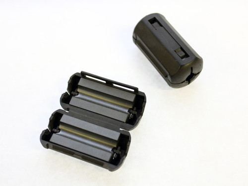
Yes on the coax becoming a radiating part of the antenna unless you choke it. If you use three snap on ferrites of a #43 mix right where the coax exits the dipole it should provide a useful choking impedance at VHF and help isolate the coax from the antenna.I think the balun/matching are going to be particularly important to giving you a "clean" directional pattern instead of having the feed line become part of the antenna. The dimensions of the elements and spacing are all relatively flexible, and will affect the exact forward gain, front-to-back ratio, side lobes, etc.. You're not going to see much difference in actual use as long as you're within a cm or two.
If you can transmit into it and read the VSWR, that would be even better. Start with a driven element a little longer than calculated. Read VSWR, chop a cm off each end of the driven element, read VSWR again. If it went down, repeat; if it went up, stop. If you want, you could waste some tape and go back half-way to the previous length, etc. When doing this, remember that things around the antenna will affect it, so tuning it outside, at least a couple meters away from things, is best.
You might also consider a corner reflector, which is particularly directional, though somewhat unwieldly at VHF.
Perhaps @prcguy can chime in.
For VHF and RG-58 size coax I would use something like this with three in series giving a good 750 ohms choking impedance.
2X44-4281P2
Ferrite Toroids, Iron Powder Toroids, Ferrite Beads, Split Cores, Cable clamp-ons, Balun Cores, W2FMI Baluns and Ununs, Inductive, power supplies, HAM radio.
 www.amidoncorp.com
You could also use a single larger more expensive core that would allow three passes of coax through the hole and that would provide more choking impedance.
At least one of these sites/guys show 7 turns of RG58 cable around the PVC boom for the balun. Would that be as good as a ferrite?
mmckenna
I ♥ Ø
At least one of these sites/guys show 7 turns of RG58 cable around the PVC boom for the balun. Would that be as good as a ferrite?
I was in a jam a few years back and needed a UHF Yagi to do some quick-n-dirty direction finding on some interference. Trying to drag around a commercial Yagi antenna with stiff elements, pulling it in and out of a truck, plus the cost, delays in purchasing, etc. made it a not so good solution.
In an evening, I slapped together one of these tape measure antennas. Even used a "free" tape measure from Harbor Freight. I did the turns around the boom to decouple the antenna from the coax.
It worked well enough that I was able to find the offender and get it resolved. I was able to throw it in the back of the truck and not worry about it getting damaged. I hit it with a rattle can of black spray paint so it didn't look too dorky.
Not a bad solution for tracking down noise.
How much of a improvement would a core make?? Considering this isn't meant for xmit.
Ubbe
Member
The number of turns and size are frequency dependent and are not so effective, perhaps it manage a 100 or 150 ohm decouple of the outer braid if you get the windings optimized.At least one of these sites/guys show 7 turns of RG58 cable around the PVC boom for the balun. Would that be as good as a ferrite?
You can often get a free sample from MiniCircuit if you request a solder type of transformer balun. Then you get a 100% decoupling and a more efficient antenna. You can hot glue it to the antenna.
/Ubbe
Ferrite absorbs RF and turns it into heat. Just the right amount of turns in the coax can make a choke for a very specific frequency but it will be reflective sending common mode currents back toward the driven element and at best they are not that effective. Especially when not tuned with test equipment. Ferrite is a much better solution.At least one of these sites/guys show 7 turns of RG58 cable around the PVC boom for the balun. Would that be as good as a ferrite?
Then which is better; a balun, matching network or neither as this is receive only? All of those choices in that MiniCircuits page is beyond confusing.
- Status
- Not open for further replies.
Similar threads
- Replies
- 4
- Views
- 292