A matching transformer can have some common mode rejection depending on its design. A common mode filter like snap on ferrite beads over the coax is specifically for reducing common mode currents and isolating the antenna from the feedline.Then which is better; a balun, matching network or neither as this is receive only? All of those choices in that MiniCircuits page is beyond confusing.

-
To anyone looking to acquire commercial radio programming software:
Please do not make requests for copies of radio programming software which is sold (or was sold) by the manufacturer for any monetary value. All requests will be deleted and a forum infraction issued. Making a request such as this is attempting to engage in software piracy and this forum cannot be involved or associated with this activity. The same goes for any private transaction via Private Message. Even if you attempt to engage in this activity in PM's we will still enforce the forum rules. Your PM's are not private and the administration has the right to read them if there's a hint to criminal activity.
If you are having trouble legally obtaining software please state so. We do not want any hurt feelings when your vague post is mistaken for a free request. It is YOUR responsibility to properly word your request.
To obtain Motorola software see the Sticky in the Motorola forum.
The various other vendors often permit their dealers to sell the software online (i.e., Kenwood). Please use Google or some other search engine to find a dealer that sells the software. Typically each series or individual radio requires its own software package. Often the Kenwood software is less than $100 so don't be a cheapskate; just purchase it.
For M/A Com/Harris/GE, etc: there are two software packages that program all current and past radios. One package is for conventional programming and the other for trunked programming. The trunked package is in upwards of $2,500. The conventional package is more reasonable though is still several hundred dollars. The benefit is you do not need multiple versions for each radio (unlike Motorola).
This is a large and very visible forum. We cannot jeopardize the ability to provide the RadioReference services by allowing this activity to occur. Please respect this.
You are using an out of date browser. It may not display this or other websites correctly.
You should upgrade or use an alternative browser.
You should upgrade or use an alternative browser.
Specific interference on the VHF Business High band
- Thread starter videobruce
- Start date
- Status
- Not open for further replies.
Ubbe
Member
State a frequency range, 100-200MHz, 50 or 75 ohm and DC isolation and configuration A-B-C doesn't matter. Impedance ratio 1 up to 1.5 that means that if you get a 50 ohm type it will be 75 ohm with a 1.5 ratio that will equal a dipoles impedance or the non folded driven element in a yagi. Connect to the outer windings and do not use center if the transformer has that. Devices that are EZ marked can be had as samples. Select a cheap one like $2 and then state in a document they provide that you are gonna use it for an antenna experiment.Then which is better; a balun, matching network or neither as this is receive only? All of those choices in that MiniCircuits page is beyond confusing.
You can get something like this with 1dB insertion loss that they have 16000 of: 1:1 CORE & WIRE Transformer, 1.5 - 500 MHz, 50Ω | TC1-1+ | Mini-Circuits
/Ubbe
Done, I'll see what happens.
Most (all?) of the Mini-Circuits EZSamples are tiny surface-mount devices, which may be a challenge to use. The example Ubbe gave is less than 5 mm in all dimensions. I'd stick with the wire/coax-based solutions.
Sounds like that isn't going to do it, thou it didn't look the case by the photo shown in his link.
I still don't get the deal with that 'U' matching network, especially the size/length?
I want to get it right the 1st time, I don't want to tweak it to death. I have the parts it came to $38 w/o the 1/2" tubing and the RG-58 w/ a BNC fitting which I already had.
Really frustrating. Every time I hear from someoen else, it's a different story, how many ways can one make chocolate milk?
Last edited:
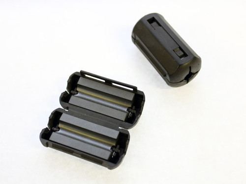
With these, the cable runs straight thru, no wrapping?For VHF and RG-58 size coax I would use something like this with three in series giving a good 750 ohms choking impedance.
2X44-4281P2
Ferrite Toroids, Iron Powder Toroids, Ferrite Beads, Split Cores, Cable clamp-ons, Balun Cores, W2FMI Baluns and Ununs, Inductive, power supplies, HAM radio.www.amidoncorp.com
One or two wouldn't be enough?
Ubbe
Member
Yes, that why you hot glue it to the antenna and also the wiring to it after the soldering. Use a tie-wrap or two around the coax to secure it. It's for a temporary direction finding and not a permanent install on a mast pole, but can be used as such if put inside a weather proof box.Most (all?) of the Mini-Circuits EZSamples are tiny surface-mount devices, which may be a challenge to use. The example Ubbe gave is less than 5 mm in all dimensions. I'd stick with the wire/coax-based solutions.
/Ubbe
One does nothing, two does a little, three is just right for VHV/UHF.With these, the cable runs straight thru, no wrapping?
One or two wouldn't be enough?
Ubbe
Member
Radio signals are a wave. If you put a ferrite core where the radio wave are at it's zero point it wont help at all. If you have several cores on a row then it's a bigger chance that one of them will hit the radio wave at it's highest peak. Or if you can have a coax go several turns inside a core it will be a larger length of the coax that are covered by the ferrite and will do the same thing.
If you just coil up the coax by its own then at one point of the coil the signal will be at max positive and at another point max negative and if those points are next to each other in the coil they will cancel each other out. So that's why it will be dependent of the wavelength and will be frequency dependent.
This is when trying to make a core balun to optimize an antenna. For interferences that comes from electronic devices you'll need to cover all frequencies from VHF to UHF that your receiver and antenna handles and must have enough ferrite length to cover all those wavelengths and stop them from travelling along the coax and into the antenna, or if you have ferrite on the coax at the receiver end to stop interferences to enter the receiver.
So for the benefit of both those cases you use as many ferrites as possible. For 30MHz it will be a huge 5 meter length. I have one 450MHz yagi that came with a core balun that consists of ferrite cores of a length of 20cm, almost one feet, that seems to almost match a 1/2 wave.
/Ubbe
Ok, I built the antenna without any balun or matching 'U', just a straight run of RG-58 cable to a BNC fitting and a BNC to SMA adapter.
BUT,
Using a RF Explorer which I felt would be the best choice for portability and still give me a 'spectrum' to scan since the interference is not set on a single frequency. The 'receive' results are very poor compared to the stock telescoping 'whip' antenna that is supplied with the unit. I barely get any readings including just baseline noise. It's just a flat line for the most part with a few minor peaks here and there. I noticed this right away inside.
I first confirmed the jumper cable and the solder points, both are good. I rechecked the Explorer with their antenna and all is well. The test was done outdoors on a 2nd floor porch moving around and doing a 360 circle. This is aiming the antenna for max signal, not off the rear for a null which in no way would work unless I was less than a few hundred feet from the source.
I'm going to run some more tests and report back.
Is it that lack of a balun the issue? I was going to add one of those 'U' shorting loops to see if that changes things
Well, I added that 'U' and 7 turns of the cable per those other designs and it made matters worse (if that could even happen). I removed the 'U', no change still almost nothing. I un-wound the cable and it seems to be back the way it was, some signals, still well less then the included whip.
Ok, I'll bite, how could that cable wound 7 turns do that?
Ok, I'll bite, how could that cable wound 7 turns do that?
mmckenna
I ♥ Ø
It took me a lot of trial and error with the hairpin match.
Mine was tuned for 465MHz, so working off the online guides, doing some maths, and it still took some time with the antenna analyzer to get it right.
3 elements, so not a real tight pattern, but it was good enough to RDF the offending transmitter and get near enough that I could narrow it down with other means.
Just to confirm, you did cut the driven element at the feed point, with the coax center conductor connected to the top half and the shield connected to the bottom half, right? Without the hairpin match, there should be very high resistance between the center conductor and the shield of the coax. Are you sure your cable and adapters are good?
Ubbe
Member
Seems like you only get reception from the coax alone and not from the antenna elements. There has to be some sort of short circuit as two metal elements connected to a coax should work equal to the antenna on the scanner, and even better when you get the match done properly.Ok, I'll bite, how could that cable wound 7 turns do that?
/Ubbe
Whenever I make up most any 'patch cords' especially for RF, I almost always check resistance of the center conductor, then the shield/ground and lastly for a short between the center and shield.
Note I said "almost".
There was a dead short across the BNC fitting. All is apparent well.
I did some initial tests using the local US Weather Service (162.55) as a reference signal since it's continuous and found differences with and w/o the 7 turn coil and/or tat 'U' shaped shorting jumper. It seems sensitivity is slightly better w/ the U jumper in place. The 'coil' mod did seem to change things, but not apparently for the better.
Note I said "almost".
There was a dead short across the BNC fitting.
All is apparent well.I did some initial tests using the local US Weather Service (162.55) as a reference signal since it's continuous and found differences with and w/o the 7 turn coil and/or tat 'U' shaped shorting jumper. It seems sensitivity is slightly better w/ the U jumper in place. The 'coil' mod did seem to change things, but not apparently for the better.
The U is for matching and will raise the impedance. A dipole sandwiched between other elements in a Yagi can be in the 25 ohm range and the hairpin match can bring that up to the 50 ohm range but you have to tune its length. The hairpin match will not affect directionality on the antenna but if the match is really bad the coax can interact more and radiate.Whenever I make up most any 'patch cords' especially for RF, I almost always check resistance of the center conductor, then the shield/ground and lastly for a short between the center and shield.
Note I said "almost".
There was a dead short across the BNC fitting.
I did some initial tests using the local US Weather Service (162.55) as a reference signal since it's continuous and found differences with and w/o the 7 turn coil and/or tat 'U' shaped shorting jumper. It seems sensitivity is slightly better w/ the U jumper in place. The 'coil' mod did seem to change things, but not apparently for the better.
Shortening the U raises or lowers the impedance?
I don’t know. I start with some #12 wire longer than needed and trim it for the best match, then make a permanent one out of copper or aluminum. The length is not super critical.Shortening the U raises or lowers the impedance?
Yes.Shortening the U raises or lowers the impedance?
Seriously, if someone tries to show you a Smith chart, run screaming in the other direction. 😨
- Status
- Not open for further replies.
Similar threads
- Replies
- 4
- Views
- 515
- Replies
- 12
- Views
- 1K