digitalanalog
Active Member
-Topic Note-
In a previous thread I did some RG6 coax testing and it was determined that the NanoVNA is a 50 ohm testing device so trying to test 75 ohm RG6 was not going to give (for lack of better terminology) Normal or Usable data as a result.
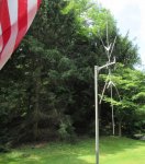
The ST2 Scantenna, This is one of the original ones with the blcak insulators
Per the Mfg Owners manual.
"Your antenna has elements which are resonant in the 30-54MHz, 108-174 MHz, 450-470 MHz, 470-512 MHz, and 800-912 MHz bands.
They work together to give you a frequency coverage from 30 MHz to 1300 MHz.
Supplied with 50' of RG-6 Coaxial Cable."
So I tested my ST-2 antenna with 25' of new RG-6 coax.
-Testing Conditions-
Sunny skies 80-85 degrees F, Using a Tripod, Using 2" dia. steel mast pipe at 10' long, ST-2 antenna mounted at 9'-11" to the center of the antenna square tube, Steel mast pipe was leveled, antenna was leveled, antenna facing North-Northwest.
-VNA-
NanaoVNA Harware Version 3.4; coverage 50k - 1.5GHz.
Test results are from the VNA and NOT from NanoVNA associated computer software.
-Testing-
Using the Resonant information from the Mfg. I tested only those area's.
I documented ONLY the starting point, any Dips (low points on the VNA) any Peaks(high points on the VNA),and the Ending Point.
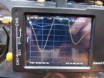
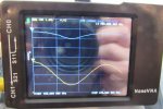
Blue line on the Images is the LogMag Return Loss 10/db, the Yellow line is the SWR 1.0.


- 30-54 Mhz -
Start: 30.000 Mhz. - SWR: 7.74 - LogMag: -2.22db
Dip: 34.560 Mhz. - SWR: 2.99 - LogMag: -6.06db
Peak: 39.840 Mhz. - SWR: 8.99 - LogMag: -1.93db
Peak: 45.360 Mhz. - SWR: 9.75 - LogMag: -1.78db
Dip: 49.440 Mhz. - SWR: 4.55 - LogMag: -3.87db
Ending: 54.000 Mhz. - SWR: 6.65 - LogMag: -2.63db

- 108 - 174 Mhz -
Start: 108.000 Mhz - SWR: 1.65 - LogMag: -2.22db
Dip: 109.320 Mhz - SWR: 1.33 - LogMag: -16.79db
Peak: 114.600 Mhz - SWR: 2.56 - LogMag: -7.14db
Dip: 122.520 Mhz. - SWR: 1.12 - LogMag: -24.32db
Peak: 128.460 Mhz. - SWR: 2.54 - LogMag: -7.20db
Dip: 135.720 Mhz. - SWR: 1.13 - LogMag: -23.83 db
Peak: 142.320 Mhz. - SWR: 2.70 - LogMag: -6.72db
Dip: 150.240 Mhz. - SWR: 1.26 - LogMag: -18.68db
Peak: 156.840 Mhz. - SWR: 2.78 - LogMag: -6.53db
Dip: 164.100 Mhz. - SWR: 1.20 - LogMag: -20.79db
Peak: 170.800Mhz. - SWR: 2.41 - LogMag: -7.66db
Ending: 174.000 Mhz. - SWR: 1.92 - LogMag: -10.00db

- 450 - 470 Mhz. -
Start: 450.000 Mhz - SWR: 4.41 - LogMag: -4.00db
Dip: 458.200 Mhz. - SWR: 1.83 - LogMag: -10.57db
Peak: 466.000 Mhz. - SWR: 4.15 - LogMag: -4.25db
Ending: 470.000 Mhz. - SWR: 3.21 - LogMag: -5.58db

- 470 - 512Mhz -
Start: 470.000 Mhz. - SWR: 1.55 - LogMag: -5.58db
Dip: 474.200 Mhz. - SWR: 1.77 - LogMag: -11.08db
Peak: 481.760 Mhz. - SWR: 3.98 - LogMag: -4.44db
Dip: 490.500 Mhz. - SWR: 1.85 - LogMag: -10.46db
Peak: 498.140 Mhz. - SWR: 4.10 - LogMag: -4.28db
Dip: 506.540 Mhz. - SWR: 1.86 - LogMag: -10.41db
Ending: 512.000 Mhz - SWR: 3.63 - LogMag: -4.95db

- 800 - 912 Mhz -
Start: 800,000 Mhz, - SWR: 1.55 - LogMag: -13.24db
Peak: 803.360 Mhz. - SWR: 1.72 - LogMag: -11.50db
Dip: 810.080 Mhz. - SWR: 1.22 - LogMag: -20.05db
Peak: 819.040 Mhz. - SWR:2.18 - LogMag: - 8.58db
Dip: 828.000 Mhz. - SWR: 1.24 - LogMag: -19.13db
Peak: 835.840 Mhz. - SWR: 2.01 - LogMag: -9.44db
Dip: 843.680 Mhz. - SWR: 1.45 - LogMag: -14.62db
Peak: 851.520 Mhz. - SWR: 1.70 - LogMag: -11.71db
Dip: 861.600 Mhz. - SWR: 1.38 - LogMag: -15.72db
Peak: 871.600 Mhz. - SWR: 1.65 - LogMag: -12.11db
Dip: 880.640 Mhz. - Swr: 1.28 - LogMag: -18.02db
Peak: 889.600 Mhz. - SWR: 2.04 - LogMag: -9.27db
Dip: 898.560 Mhz. - SWR: 1.12 - LogMag: -24.77db
Peak: 906.400 Mhz. - SWR: 2.18 - LogMag: -8.61db
Ending: 912.000 Mhz. - SWR: 1.31 - LogMag: -17.42db
The fact that most of us do not have high dollar antenna testers and the availability of the NanoVNA as seen time and time
again in many locations this is what is being used to test antennas and other antenna related components.
No, the ST-2 people did not use a Nano to test with, But by today's standards it's what people can afford and what they are using.
While some of these numbers may not agree with the Mfg Resonant points, the NanoVNA has done the testing. I simply installed
the antenna and the coax.
Will others get the same numbers if they test with a NanoVNA, The answer I believe is NO, every situation is different and no 2 test results
will be the same, close yes, the same I doubt it.
I simply turned the antenna after testing was done and looked at a few numbers I had documented, and just by turning the antenna it changed the numbers........
In a previous thread I did some RG6 coax testing and it was determined that the NanoVNA is a 50 ohm testing device so trying to test 75 ohm RG6 was not going to give (for lack of better terminology) Normal or Usable data as a result.
The ST2 Scantenna, This is one of the original ones with the blcak insulators
Per the Mfg Owners manual.
"Your antenna has elements which are resonant in the 30-54MHz, 108-174 MHz, 450-470 MHz, 470-512 MHz, and 800-912 MHz bands.
They work together to give you a frequency coverage from 30 MHz to 1300 MHz.
Supplied with 50' of RG-6 Coaxial Cable."
So I tested my ST-2 antenna with 25' of new RG-6 coax.
-Testing Conditions-
Sunny skies 80-85 degrees F, Using a Tripod, Using 2" dia. steel mast pipe at 10' long, ST-2 antenna mounted at 9'-11" to the center of the antenna square tube, Steel mast pipe was leveled, antenna was leveled, antenna facing North-Northwest.
-VNA-
NanaoVNA Harware Version 3.4; coverage 50k - 1.5GHz.
Test results are from the VNA and NOT from NanoVNA associated computer software.
-Testing-
Using the Resonant information from the Mfg. I tested only those area's.
I documented ONLY the starting point, any Dips (low points on the VNA) any Peaks(high points on the VNA),and the Ending Point.
Blue line on the Images is the LogMag Return Loss 10/db, the Yellow line is the SWR 1.0.


- 30-54 Mhz -
Start: 30.000 Mhz. - SWR: 7.74 - LogMag: -2.22db
Dip: 34.560 Mhz. - SWR: 2.99 - LogMag: -6.06db
Peak: 39.840 Mhz. - SWR: 8.99 - LogMag: -1.93db
Peak: 45.360 Mhz. - SWR: 9.75 - LogMag: -1.78db
Dip: 49.440 Mhz. - SWR: 4.55 - LogMag: -3.87db
Ending: 54.000 Mhz. - SWR: 6.65 - LogMag: -2.63db

- 108 - 174 Mhz -
Start: 108.000 Mhz - SWR: 1.65 - LogMag: -2.22db
Dip: 109.320 Mhz - SWR: 1.33 - LogMag: -16.79db
Peak: 114.600 Mhz - SWR: 2.56 - LogMag: -7.14db
Dip: 122.520 Mhz. - SWR: 1.12 - LogMag: -24.32db
Peak: 128.460 Mhz. - SWR: 2.54 - LogMag: -7.20db
Dip: 135.720 Mhz. - SWR: 1.13 - LogMag: -23.83 db
Peak: 142.320 Mhz. - SWR: 2.70 - LogMag: -6.72db
Dip: 150.240 Mhz. - SWR: 1.26 - LogMag: -18.68db
Peak: 156.840 Mhz. - SWR: 2.78 - LogMag: -6.53db
Dip: 164.100 Mhz. - SWR: 1.20 - LogMag: -20.79db
Peak: 170.800Mhz. - SWR: 2.41 - LogMag: -7.66db
Ending: 174.000 Mhz. - SWR: 1.92 - LogMag: -10.00db

- 450 - 470 Mhz. -
Start: 450.000 Mhz - SWR: 4.41 - LogMag: -4.00db
Dip: 458.200 Mhz. - SWR: 1.83 - LogMag: -10.57db
Peak: 466.000 Mhz. - SWR: 4.15 - LogMag: -4.25db
Ending: 470.000 Mhz. - SWR: 3.21 - LogMag: -5.58db

- 470 - 512Mhz -
Start: 470.000 Mhz. - SWR: 1.55 - LogMag: -5.58db
Dip: 474.200 Mhz. - SWR: 1.77 - LogMag: -11.08db
Peak: 481.760 Mhz. - SWR: 3.98 - LogMag: -4.44db
Dip: 490.500 Mhz. - SWR: 1.85 - LogMag: -10.46db
Peak: 498.140 Mhz. - SWR: 4.10 - LogMag: -4.28db
Dip: 506.540 Mhz. - SWR: 1.86 - LogMag: -10.41db
Ending: 512.000 Mhz - SWR: 3.63 - LogMag: -4.95db

- 800 - 912 Mhz -
Start: 800,000 Mhz, - SWR: 1.55 - LogMag: -13.24db
Peak: 803.360 Mhz. - SWR: 1.72 - LogMag: -11.50db
Dip: 810.080 Mhz. - SWR: 1.22 - LogMag: -20.05db
Peak: 819.040 Mhz. - SWR:2.18 - LogMag: - 8.58db
Dip: 828.000 Mhz. - SWR: 1.24 - LogMag: -19.13db
Peak: 835.840 Mhz. - SWR: 2.01 - LogMag: -9.44db
Dip: 843.680 Mhz. - SWR: 1.45 - LogMag: -14.62db
Peak: 851.520 Mhz. - SWR: 1.70 - LogMag: -11.71db
Dip: 861.600 Mhz. - SWR: 1.38 - LogMag: -15.72db
Peak: 871.600 Mhz. - SWR: 1.65 - LogMag: -12.11db
Dip: 880.640 Mhz. - Swr: 1.28 - LogMag: -18.02db
Peak: 889.600 Mhz. - SWR: 2.04 - LogMag: -9.27db
Dip: 898.560 Mhz. - SWR: 1.12 - LogMag: -24.77db
Peak: 906.400 Mhz. - SWR: 2.18 - LogMag: -8.61db
Ending: 912.000 Mhz. - SWR: 1.31 - LogMag: -17.42db
The fact that most of us do not have high dollar antenna testers and the availability of the NanoVNA as seen time and time
again in many locations this is what is being used to test antennas and other antenna related components.
No, the ST-2 people did not use a Nano to test with, But by today's standards it's what people can afford and what they are using.
While some of these numbers may not agree with the Mfg Resonant points, the NanoVNA has done the testing. I simply installed
the antenna and the coax.
Will others get the same numbers if they test with a NanoVNA, The answer I believe is NO, every situation is different and no 2 test results
will be the same, close yes, the same I doubt it.
I simply turned the antenna after testing was done and looked at a few numbers I had documented, and just by turning the antenna it changed the numbers........


