Tecsun Want to align Shortwave Frequency PL-600

Status
Not open for further replies.
S

simpilo

Guest
I am looking for advice on which component(s) to adjust to bring the radio to a more precise accurate reading. The radio is receiving 2khz lower than actual frequency displayed. If I tuned to 10000khz WWV I get the signal but as I tune down I noticed the signal level increaes then the audio clears up. If I tune upward from 10000khz it cliffs.

I found these PL-600 Schematics. I hope someone with experience can figure out and tell me which component(s) needs to be adjusted to bring the radio into more precise tuning. Thanks very much!
 

Attachments

  • schematic (2).pdf
    32.8 KB · Views: 23
  • schematic (3).pdf
    94.4 KB · Views: 17
  • schematic (4).pdf
    127.9 KB · Views: 18
Last edited:

jaspence

Member
Premium Subscriber
Joined
Mar 21, 2008
Messages
3,041
Location
Michigan
Adjustments like this usually require more than a screw driver and some instructions. An oscilloscope or some other electronic device is usually needed for satisfactory results, and it may require more than one component needing adjustment.
 
S

simpilo

Guest
There's a YouTube video dealing with frequency calibration on the PL-600

Thats not the correct way. I already seen it. Both red trimmers are BFO adjustments. Adjusting those two for AM mode throws off the BFO up 1khz. I am thinking its a troll video. He may know the right way but being hard headed about it.
 

majoco

Stirrer
Joined
Dec 25, 2008
Messages
4,315
Location
New Zealand
I though we'd had this out before! I have PL600 and it shows the same effect. If you listen to any AM station with the selectivity switch set to 'narrow' you'll find the it sounds best right on frequency - but when you switch to 'wide' it sounds best 1kHz down - well, mine does. So the problem is in the wide ceramic filter not being centred on the IF frequency - the filters are bottom right on schematic (4). Those filters are probably the cheapest you can get so perhaps if you search around for a better quality filter you might solve the problem.
 
S

simpilo

Guest
I though we'd had this out before! I have PL600 and it shows the same effect. If you listen to any AM station with the selectivity switch set to 'narrow' you'll find the it sounds best right on frequency - but when you switch to 'wide' it sounds best 1kHz down - well, mine does. So the problem is in the wide ceramic filter not being centred on the IF frequency - the filters are bottom right on schematic (4). Those filters are probably the cheapest you can get so perhaps if you search around for a better quality filter you might solve the problem.
Exact same problem I speak of in this thread. Thankfully, I didn't touch the IF alignment LOL! I bet CF1 455G is the culprit! I wish I could find a parts list to reference '455G' component value. Seems like 455khz but not to sure. Weird thing is the reference frequency is 456khz! Ty Majoco!!
 
Last edited:

majoco

Stirrer
Joined
Dec 25, 2008
Messages
4,315
Location
New Zealand
Google for "MuRata ceramic resonator 455G" and you'll have more than you know what to do with! I recall that the "G" refers to the bandwidth.
 
S

simpilo

Guest
Google for "MuRata ceramic resonator 455G" and you'll have more than you know what to do with! I recall that the "G" refers to the bandwidth.

Wish they made 3 pin variable CF's due to the radio's odd reference frequency. I am having issues finding the right part on Murata's website. I don't like how they did layed it out. needs to be tuned 456khz with 1.711MHZ-29.999MHZ. All they have wide banded but not enough.

I have found 455G 3 pin looks similar to what's in the radio roughly. Ill have to open PL-600 to see. Should be a easy find. Still may not be the centered on the I.F frequency. For Sale: Crystals
455G.PNG
 
Last edited:

majoco

Stirrer
Joined
Dec 25, 2008
Messages
4,315
Location
New Zealand
Why do you want it to be tuned to 456kHz centre frequency? The schematic diagram says 455kHz and I'm reasonably certain that's what the CF is, IMHO the one in the radio is off-frequency.
 
S

simpilo

Guest
Why do you want it to be tuned to 456kHz centre frequency? The schematic diagram says 455kHz and I'm reasonably certain that's what the CF is, IMHO the one in the radio is off-frequency.
It looked like 456 in the schematic. It's not a high resolution schematic either. I hadn't aimed to tune it to 456khz. I want to get it back on track. I looked inside the radio and found CF1 not to be a Murata CF but It's a different CTE or CTX. 455IF I believe was what the top of it said. Its a black omponent sitting next to a variable I.F. transformer.

@jwt873
As far as the video is concerned, Those two trimmer VC1 and VC5 are tied in with the 75khz tubular crystal that is tied to PINS 19 and 20 LC72137M. Looks like it has something to do with the n-channel MOS transistor used for the PLL active low-pass filter. !!!!! Will cause the Data Shift Registers to go out of whack!!! It may seem like frequency is shifting but your actually throwing off the PLL lock!!!!! The way it is implemented is way to far from that I.C. those three components should be right next to pins 19&20 per Sanyo's Datasheet!!! Thats part of the problem with noise!!!

It's not what I said after some deeper research. BFO is somewhere around 2Q11.
 
Last edited:
S

simpilo

Guest
Why do you want it to be tuned to 456kHz centre frequency? The schematic diagram says 455kHz and I'm reasonably certain that's what the CF is, IMHO the one in the radio is off-frequency.
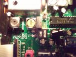
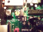
CXE 455IK.. I havent removed the main PCB from the chassis to find out what sort of pinout it needs for cross reference for a similar equivalent part.
 

Attachments

  • IMG_20190706_082426.jpg
    IMG_20190706_082426.jpg
    121.1 KB · Views: 17

majoco

Stirrer
Joined
Dec 25, 2008
Messages
4,315
Location
New Zealand
CF2 is the suspect wide filter, not CF1. I didn't expect any of them to be made by MuRata, they're the expensive ones - relatively speaking.
 

majoco

Stirrer
Joined
Dec 25, 2008
Messages
4,315
Location
New Zealand
Have you tried tweaking the second oscillator frequency - it supposedly produces 55.390MHz and mixes with the 55.845MHz signal to produce 455kHz for the filters - but it's a bit off then it won't. It's VC2 in that box above the filters in schematic (4).
 
S

simpilo

Guest
Have you tried tweaking the second oscillator frequency - it supposedly produces 55.390MHz and mixes with the 55.845MHz signal to produce 455kHz for the filters - but it's a bit off then it won't. It's VC2 in that box above the filters in schematic (4).
I didnt touch it. I need some test equipment that can read that. I am afraid to make it worse. IF those filters are bad it wouldnt make a difference tweaking it. I found a russian forums website. I forgot the url to it. Some user there uploaded an image with different filters installed in it. I think more components need to be tested as well. Actively considering and reconsidering what to do with it. Being very careful. Living with the 2khz offset until I can afford the tools. Tweaking VC1 and VC5 zero beat fine which leads me to kind of think it is those filters. Both of those filters. I wouldnt overlook those caps as well. 75khz reference may have been off too. I also want to check solder joints. I hope its a joint not properly soldered. 75khz reference can be readjusted. If those filters are bad then the side effect of the 75khz reference frequency seemingly off beat can always be readjusted back if replacing the filters work.

I might try the "finger to solder joints" trick on the proper solder joints to see if it drifts any touching the solder joints to VC2. If so, then I'll try it. Kind of doubt that'll work.
 
Last edited:
S

simpilo

Guest
Have you tried tweaking the second oscillator frequency - it supposedly produces 55.390MHz and mixes with the 55.845MHz signal to produce 455kHz for the filters - but it's a bit off then it won't. It's VC2 in that box above the filters in schematic (4).
That VC trimmer is tight. I cant adjust it. Won't budget. I don't strong arm these.
 
S

simpilo

Guest
Does the lead to D7 (diode) look broken to anyone else?
 

Attachments

  • IMG_20190706_082426.jpg
    IMG_20190706_082426.jpg
    121.1 KB · Views: 13

majoco

Stirrer
Joined
Dec 25, 2008
Messages
4,315
Location
New Zealand
Did you spot that before you took the pic, or just by looking at the pic? IMHO it's just a bright bit of the lead.
 
Status
Not open for further replies.
Top