Wideband Multicoupler Build Project

Status
Not open for further replies.

K4APR

Member
Joined
Apr 18, 2003
Messages
1,028
Location
Chesapeake, VA.
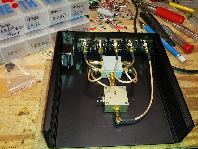
I just completed a build project tonight of a wideband (0-1000MHz) four port multicoupler. The unit consists of a Mini Circuits ZFL1000 +20dB pre-amp and Mini Circuits ZFSC-4 four port splitter. The case is an extruded aluminum case by Hammond, with a removable top plate (makes installing everything MUCH easier). The front and rear plates were milled on my in-house CNC machine. I used N Female to SMA female chasis mount connectors for both the input and output ports. I decided to put a small +15VDC switching supply inside of the unit, so I added a standard equipment power cable socket with built-in noise filtering.

I plan to do some more bench testing with an RF signal source and spectrum analyzer. In the meantime, here are some pictures of the build:

FB_IMG_13724548224257185.jpg


FB_IMG_13735771379928566.jpg


FB_IMG_13735771496779372.jpg


FB_IMG_13735774101579596.jpg


FB_IMG_13741003770641090.jpg


FB_IMG_13741003853251399.jpg


FB_IMG_13741014742491558.jpg


FB_IMG_13741014831125097.jpg
 

gmclam

Member
Premium Subscriber
Joined
Sep 15, 2006
Messages
6,429
Location
Fair Oaks, CA
Nice

Very nice job and photo essay. :)

Why did you decide to go the route of building your own, rather than an off-the-shelf solution? Just curious. Thanks
 

mancow

Member
Database Admin
Joined
Feb 19, 2003
Messages
6,908
Location
N.E. Kansas
That looks amazing. I would whip up a few and start selling them here.
I really wish I had a CNC setup. What type are you using?
 

prcguy

Member
Premium Subscriber
Joined
Jun 30, 2006
Messages
16,649
Location
So Cal - Richardson, TX - Tewksbury, MA
Very nice craftsmanship! Judging from the components and hardware you used I would guess you do this kind of work for a living.

However I have several ZFL1000 amps and have tried them as antenna preamps and without some bandpass filters they overload easy and produce all kinds of intermod problems. A antenna multicoupler usually has about 0dB gain throughput and with 20dB of amp gain you will still have about 14dB gain after the splitter.

The power supply looks like a Meanwell brand and I have also had problems with RFI in the HF bands from Meanwell supplies. Checking the output with a spectrum analyzer and the input terminated could be surprising.

Really good job otherwise!
prcguy
 
Last edited:

K4APR

Member
Joined
Apr 18, 2003
Messages
1,028
Location
Chesapeake, VA.
That is just awesome I wish I had the skills and patience to do that.Awesome work it looks fantastic.

Very nice job and photo essay.

That looks amazing.

Very nice craftsmanship! Judging from the components and hardware you used I would guess you do this kind of work for a living.

Thanks all! I work in the RF Communications lab at the NASA Wallops Flight Facility, so I have been around the block one or two times. I actually had plenty of experience with multicouplers in my former time as a Motorola tech.

Why did you decide to go the route of building your own, rather than an off-the-shelf solution?

I had actually looked at the Stridsberg units, but I was un-happy with the form factor, price and it seemed like many of them have front-end issues. I had the LNA and splitter already in my junk box and I knew that the housing would be a breeze with the CNC, so I decided to build my own.

I really wish I had a CNC setup. What type are you using?

My machine is a converted Harbor Freight X2 machine:


Here is the photo album of the whole conversion of the X2 and ground-up build of the controller:

https://plus.google.com/photos/113809007504325878104/albums/5629742007032981681?banner=pwa

The power supply looks like a Meanwell brand and I have also had problems with RFI in the HF bands from Meanwell supplies. Checking the output with a spectrum analyzer and the input terminated could be surprising.

It is a Meanwell. I have had good luck with them in general, but this is the first one for an RF application. I actually brought the whole unit into work today to look at it with my spectrum analyzer to see if there is any RFI/induced noise. I'll report back what I find.
 
Last edited by a moderator:

gmclam

Member
Premium Subscriber
Joined
Sep 15, 2006
Messages
6,429
Location
Fair Oaks, CA
Good catch

However I have several ZFL1000 amps and have tried them as antenna preamps and without some bandpass filters they overload easy and produce all kinds of intermod problems.
I agree. I would at least filter/reduce the FM broadcast band, and if the passband of the amplifier includes other broadcast (AM for example), I'd filter that too.
 

K4APR

Member
Joined
Apr 18, 2003
Messages
1,028
Location
Chesapeake, VA.
Here are some quick spectrum analyzer captures I did right before lunch. -50dB input:

150 MHz:

a.bmp


300 MHz:

B.bmp


450 MHz:

C.bmp


700 MHz:

D.bmp


850 MHz:

E.bmp


950 MHz:

F.bmp


I'll look into the band pass filters if I end up having intermod problems.
 

gmclam

Member
Premium Subscriber
Joined
Sep 15, 2006
Messages
6,429
Location
Fair Oaks, CA
What is the low pass band frequency of this unit? I heavily monitor CHP which is ~40MHz and need something that low. I'm using a filter from ScannerMaster that is both 25MHz HP and band rejection of FM (88-108). It works for me. Without the FM broadcast reduction, those signals heavily swamped the amp.
 

prcguy

Member
Premium Subscriber
Joined
Jun 30, 2006
Messages
16,649
Location
So Cal - Richardson, TX - Tewksbury, MA
It would be good to see a 1MHz to 30MHz shot with input terminated and the narrowest analyzer RBW and accompanying VBW to get the analyzer noise floor down to -100dBm or lower if possible. That will expose potentially harmful interference from the switching power supply.

Remember, your scanners will pick up signals down around -120dBm so you need to get the the analyzer noise floor way down to see them. Your current noise floor near -60dBm is nearly 10dB over S-9, so there could be huge interference that is not visible right now.
prcguy


Here are some quick spectrum analyzer captures I did right before lunch. -50dB input:

150 MHz:

300 MHz:

450 MHz:

700 MHz:

850 MHz:

950 MHz:

I'll look into the band pass filters if I end up having intermod problems.
 
Last edited by a moderator:

K4APR

Member
Joined
Apr 18, 2003
Messages
1,028
Location
Chesapeake, VA.
Here is what the unit looks like at the edges of the FM broadcast band:

Broadcast 88 MHz:

Broadcast-88.bmp


Broadcast 108 MHz:

Broadcast-108.bmp


Hooked up an antenna for some on-air tests. These are just some common ranges that I wanted to look at. The frequency range of the LNA is theoretically 0-1000 MHz.

3-30 MHz HF:

hf.bmp


88-108 MHz Broadcast:

broad.bmp


150-200 MHz VHF Commercial, ect:

VHF+150-200.bmp


vhfcom.bmp


100-200 MHz VHF Amateur, Commercial, ect:

vhf+wide.bmp
 
Last edited:

K4APR

Member
Joined
Apr 18, 2003
Messages
1,028
Location
Chesapeake, VA.
It would be good to see a 1MHz to 30MHz shot with input terminated and the narrowest analyzer RBW and accompanying VBW to get the analyzer noise floor down to -100dBm or lower if possible. That will expose potentially harmful interference from the switching power supply.

Here is the best that I could get out of my bench Rigol SA:

hffloor.bmp
 

prcguy

Member
Premium Subscriber
Joined
Jun 30, 2006
Messages
16,649
Location
So Cal - Richardson, TX - Tewksbury, MA
Looking at your plots with an antenna connected I see quite a few really hot carriers above -10dBm in the FM broadcast band and also the public service band. Since you have a 4-way divider after the amp those -10dBm signals are actually -4dBm or higher and I would bet the aggregate power is probably near the amp compression point and you most certainly are creating lots of intermod in the amp.

If you live out in the boonies with no transmitters nearby the ZFL1000 may work out but like me you have a lot of very strong signals right off the antenna. Out of a few dozen broad band amps I have tried for a similar purpose, only one has survived being fed from a broad band antenna like a Discone and did not create havoc for my receivers.
prcguy
 

KevinC

The big K
Super Moderator
Joined
Jan 7, 2001
Messages
12,630
Location
1 point
I believe a -10 dBm signal is officially classified as "smokin". :D

I really like your craftsmanship. What will be connected to this, scanners? I know mine don't like any signal over about -35 dBm, so you may need to pad it down some.

I've had real good luck with the Meanwell's also.
 
Last edited:

Mike_G_D

Member
Joined
Dec 19, 2002
Messages
1,244
Location
Vista, CA
I agree with all of what prcguy has said; I like your workmanship and skill (and am seriously envious of your resources at hand!) but I would really change out that amp for a much less "hot" version - really for a multicoupler intended for a broadband scanner/receiver setup I would use an amp which only compensated for the loss incurred in the splitter give or take maybe a few dB. But you did say that you were only using what you had in your spares box so I can understand why you went with that in the first go.

Given that you do have so much extra gain anyway, maybe consider finding a good high pass filter stage to go in front of the splitter (between the antenna port and the splitter); you have more than enough extra gain to play with so rolling off everything below 30MHz or so might be a good idea or even below 150MHz if low band VHF is not of interest to you. Of course switchable bandpass filters would be really nice but then we are getting way off in a more complex design area;-)!

Cool stuff, though!!! I wish like crazy that I could be there working on that with you!! With all due respect to Stridesburg, they REALLY need some competition (aimed at the scanner hobbyist market) - there is no reason that they should be having the reported recurring failure rate I have been reading about with proper attention to the relevant design areas especially give their product prices.

-Mike
 
Last edited:

commscanaus

Member
Joined
Jan 27, 2006
Messages
525
Location
Melbourne VK
Outstanding work Jason!

Your build is excellent, love the case it is mounted into and the way you have integrated everything.
As mentioned earlier, you should go into production and build a few more.
I am sure they will sell immediately!

The amplifier gain is too high for me to use here, as there is an FM broadcaster a few miles LOS to me along with some blowtorch UHF signals.
I think that the particular model Minicircuits preamplifier you have used would cause some serious pyroclastic flows from the front end of the receivers here without some serious filtering in place.

Apart from that, I would certainly like one of your multicouplers!

Regards, Commscanaus.
 

K4APR

Member
Joined
Apr 18, 2003
Messages
1,028
Location
Chesapeake, VA.
I appreciate all of the input, especially regarding the broad front-end of the LNA. I completely agree that it might not be the best choice, but as I said, it was what I had. Having said that, I'm looking for some band pass filters, but I'm not having much luck finding the ranges I would like to have. eBay was a bust, too.

I wouldn't mind finding filters in these ranges 140-170, 200-300, 440-470 and 800-950 MHz.

On the that same note, I am looking for a 440-450 band pass for the front end of our NASA Wallops Club UHF repeater. I would like to add a ZFL500 LNA that I have, but I know without the filter, I have the same problems.
 

prcguy

Member
Premium Subscriber
Joined
Jun 30, 2006
Messages
16,649
Location
So Cal - Richardson, TX - Tewksbury, MA
Keep checking Ebay, I was able to buy all the filters you mention over time at very little cost. I would also not use a ZFL-500 for a UHF preamp, its noise figure is over 5dB and you want something much better like .5dB. The IP1 is also a bit low.

Check Angle Linear for probably the best front end preamps on the planet.
prcguy


I appreciate all of the input, especially regarding the broad front-end of the LNA. I completely agree that it might not be the best choice, but as I said, it was what I had. Having said that, I'm looking for some band pass filters, but I'm not having much luck finding the ranges I would like to have. eBay was a bust, too.

I wouldn't mind finding filters in these ranges 140-170, 200-300, 440-470 and 800-950 MHz.

On the that same note, I am looking for a 440-450 band pass for the front end of our NASA Wallops Club UHF repeater. I would like to add a ZFL500 LNA that I have, but I know without the filter, I have the same problems.
 

zz0468

QRT
Banned
Joined
Feb 6, 2007
Messages
6,034
Check Angle Linear for probably the best front end preamps on the planet.

Absolutely, without a doubt.

But I don't thinking he's marketing to the amateur market anymore. And he never did have a wide band model.

I've found that some of the ARR preamps have better IP3 performance than the Mini-Circuits amps do, and they have some wide band models with very low noise figures.
 

zz0468

QRT
Banned
Joined
Feb 6, 2007
Messages
6,034
I wouldn't mind finding filters in these ranges 140-170, 200-300, 440-470 and 800-950 MHz.

Wanna get creative? Get yourself some old beater Motorola Spectras, one for VHF, one for UHF, and one for 800. You want to reject the cellular band, because those wideband cellular signals will swamp a preamp, and there's nothing there to listen to anyway.

So, pull the front end board of the Spectras, and you get a nifty ceramic filter with decent roll off at the band edges. With a little bit of work, you can bypass the active stages that follow the filter. Bonus... they're very compact.

On the that same note, I am looking for a 440-450 band pass for the front end of our NASA Wallops Club UHF repeater. I would like to add a ZFL500 LNA that I have, but I know without the filter, I have the same problems.

For a repeater, you're better off getting a cavity or two.

I second the suggestion that you NOT use a ZFL500 for that. You won't be happy with it. I've used those on HF active antennas, and had decent luck. The NF is worse than just about any receiver you'll put it in front of, so it won't actually help.
 
Status
Not open for further replies.
Top