• To anyone looking to acquire commercial radio programming software:

    Please do not make requests for copies of radio programming software which is sold (or was sold) by the manufacturer for any monetary value. All requests will be deleted and a forum infraction issued. Making a request such as this is attempting to engage in software piracy and this forum cannot be involved or associated with this activity. The same goes for any private transaction via Private Message. Even if you attempt to engage in this activity in PM's we will still enforce the forum rules. Your PM's are not private and the administration has the right to read them if there's a hint to criminal activity.

    If you are having trouble legally obtaining software please state so. We do not want any hurt feelings when your vague post is mistaken for a free request. It is YOUR responsibility to properly word your request.

    To obtain Motorola software see the Sticky in the Motorola forum.

    The various other vendors often permit their dealers to sell the software online (i.e., Kenwood). Please use Google or some other search engine to find a dealer that sells the software. Typically each series or individual radio requires its own software package. Often the Kenwood software is less than $100 so don't be a cheapskate; just purchase it.

    For M/A Com/Harris/GE, etc: there are two software packages that program all current and past radios. One package is for conventional programming and the other for trunked programming. The trunked package is in upwards of $2,500. The conventional package is more reasonable though is still several hundred dollars. The benefit is you do not need multiple versions for each radio (unlike Motorola).

    This is a large and very visible forum. We cannot jeopardize the ability to provide the RadioReference services by allowing this activity to occur. Please respect this.

XG-100M RF Circuits Discussion

Teotwaki

Member
Joined
Aug 3, 2008
Messages
549
Location
SoCal
I have a XG-100M I bought a few months back and did not immediately test. Dumb move on my part. It turns out the radio programmed fine but it had no transmit power out and no receive sensitivity. It was as if there was a big attenuator in the middle of the antenna path. I figured I would concentrate on that area first.

Today I finally cracked it open and was lucky enough to quickly find the problem.

This is a picture of the RF board that has the four RF amplifier modules from Mitsubishi. From right to left they cover in MHz: 136-174, 378-470, 440-529, 763-870. There are sets of pin diodes (white SMD blocks with a black polarity dot) used to steer their outputs back towards the antenna. Note the circuitry in the red circle. This is where the antenna connection is steered to the power amps or the receiver.
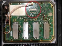
image3(2)-1.jpg

This is a sketch of what I think the basic antenna input circuit entails.
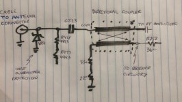
INPUT CIRCUIT-1.jpg


Here is a bit of a closer shot of that circuitry with labels on the coupler's ports. The coupler appears to be two short lengths
of rigid copper coax, each feeding through a toroid with windings. You can just see the blue wires around the toroids in the last picture below.
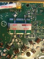
image1(13)-1.jpg

Long story short, the TX and RX ports and C378 had little to no solder
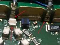
image2(8)-1.jpg


I resoldered each spot and transmit power and sensitivity are restored.
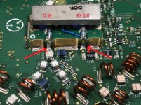
image0(27)-1.jpg

In a future post I will theorize about what I think the overall block diagram and functionality of the radio are.
 

Teotwaki

Member
Joined
Aug 3, 2008
Messages
549
Location
SoCal
Yea, great work! But I noticed in your drawing in the second picture down, you have blue ball point pen ink, black ball point pen ink and felt pen, all on the same dwg. Were you having a stroke at the time?
Changing ink was a sort of Turing test for determining which members are easily distracted by unimportant details. ;)
 

Teotwaki

Member
Joined
Aug 3, 2008
Messages
549
Location
SoCal
The pictures of the XG-100M's internals in this document will be really useful for figuring out a functional block diagram and common repairs.
 

Attachments

  • Internal-photos-1470278-FCC.pdf
    1.5 MB · Views: 12

merlin

Active Member
Joined
Jul 3, 2003
Messages
3,087
Location
DN32su
Good diagnostics. The RF board is really simple for 4 bands and a lot of people have laid out like block diagrams and functionality.
You get further upstream, it gets a lot more complicated, and the PK board is vastly more complicated yet.
Still no schematics or blocks out of Rochester as of yet. (??)
The RX/IF board binds the 700/800 Mhz and includes the VHF low.
 

merlin

Active Member
Joined
Jul 3, 2003
Messages
3,087
Location
DN32su
Yea, great work! But I noticed in your drawing in the second picture down, you have blue ball point pen ink, black ball point pen ink and felt pen, all on the same dwg. Were you having a stroke at the time?
I only see the red, everything else is factory. Or am I going color blind.
 

Teotwaki

Member
Joined
Aug 3, 2008
Messages
549
Location
SoCal
I see other components on the board that look like insufficient solder like CR135 then a huge solder blob like C378. Could be a Friday at 4:45pm solder flow job.
I tried calling you with this revived radio on your repeater so that you could be the first contact. However, you were not listening to your repeater...... or your phone, or reading email... :ROFLMAO:
 

Teotwaki

Member
Joined
Aug 3, 2008
Messages
549
Location
SoCal
I see other components on the board that look like insufficient solder like CR135 then a huge solder blob like C378. Could be a Friday at 4:45pm solder flow job.

CR135??? There is a CR153 in one of the pictures but overhead views don't really show the solder as well. Oblique views are better.
 

Teotwaki

Member
Joined
Aug 3, 2008
Messages
549
Location
SoCal
Even the inductors have very minimal solder fillets.
Open up your bricked radio and first look at the parts from straight above and pick out the ones you disapprove of. Next re- inspect them from a side view and you'll see they are fine
 

Teotwaki

Member
Joined
Aug 3, 2008
Messages
549
Location
SoCal
And...... not likely to ever happen.
That's exactly why I hesitated to open the radio up. Now that I've fixed the problem with mine I would like this thread to focus on creating a good high level block diagram and then at least the easier schematics for troubleshooting.
 

Teotwaki

Member
Joined
Aug 3, 2008
Messages
549
Location
SoCal
-----The RF board is really simple for 4 bands and a lot of people have laid out like block diagrams and functionality.
You get further upstream, it gets a lot more complicated, and the PK board is vastly more complicated yet.
---snip----
The RX/IF board binds the 700/800 Mhz and includes the VHF low
.
So where are those......
block diagrams and functionality
that so many others have laid out? I would love to see them. Links?? Pictures?? Proof??

What is the function of the Mini Circuits mixer? It's one that is rated to 1GHz for the RF and LO ports.
Mixer Circuit.jpg

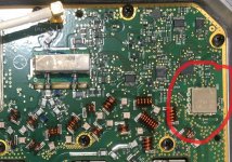
To me, the only simple part is the input circuit and the four power amps. The upper right corner of the board is quite busy with at least 10 SOICs and the Mini Circuits surface mount RF mixer on this side of the board. I suspect the main RF board (what the heck is a "PK"??) outputs at a common frequency that is then upconverted to each of the 5 bands. Harris calls this board "RES". It's in the FCC document.

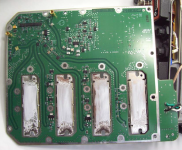
From the FCC document I linked to the back side of the PA board is quite busy too
Screenshot 2024-08-30 084006.png


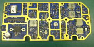
I don't believe there is a Receiver/IF board ("RX/IF") in the radio. The transmit and receive functions are probably all software defined (SD) and work on a low VHF common intermediate frequency. This RES board in the FCC document is probably the upconverter/downconverter to interface the SD portion with the PA board. I can see the GPS receiver in the upper left.
Screenshot 2024-08-30 085113.png

The SD portion is likely to be included on what Harris calls the "digital board".

If anybody has more detailed info please share the links, documents or pictures in this thread.
 
Top