12 Yagi array

Status
Not open for further replies.

VA3BBY

Member
Joined
Mar 29, 2023
Messages
45
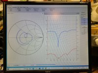
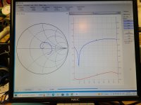
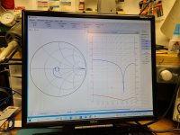
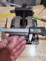
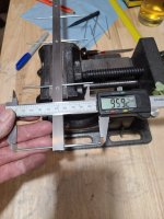
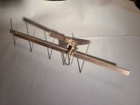
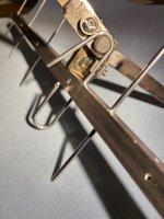
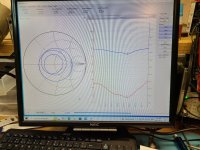
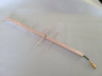
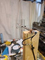
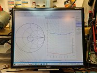
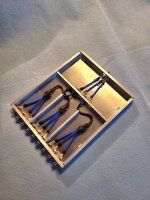
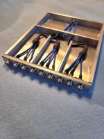
I have verified the longer elements and am satisfied I am on the right track to getting this antenna tuned see pictures 1 to 3. the difference between picture 2 and 3 is .5mm filed off elements. I worked all last Sunday trying to phase the polarizations together to no avail. The gamma match is so incredibly sensitive and trying to get both of them aligned in unison I could not accomplish. I would get close then make a wrong move and would have to start over. It seems to be 100ths of a mm that these would need equal. I turned the lights off late Sunday.

I am not sure Joel how one would deal with environmental conditions. I wonder how SKA in Australia would deal with morning dew and frigid night temperatures to desert heat in the day or how the 500m dish in China would deal with their unique weather conditions. I agree some form of variable length transmission line to fine tune would be ideal and have been thinking about how to achieve this. If radio waves can travel through rain, fog the atmosphere and stellar dust. How much impact does humidity have? An interesting question.

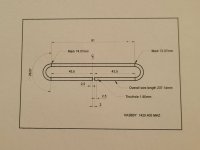
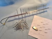
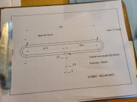
Today I made a short test antenna so I can develope a folded dipole to work with this array. I don't see any other way to match these antennas reliably. Gamma is way to sensitive with 2 polarizations and next to impossible to match together and what happens if one gets bumped by a fat bumble bee or hit with a hail stone or even bird sh_t? I have made a new mechanical bender that utilizes a sealed bearing to make the 180 degree turn repeatable and will share pictures maybe tomorrow and also what I have come up with to solder the coax to the aluminum dipole element. This development is going to take dozens of attempts to get the correct overall length, there is no adjustment in these so trial and error until it is right. Tomorrow morning I will generate a CAD drawing for reference points to use with this bender and an initial overall length to try.

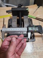
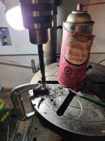
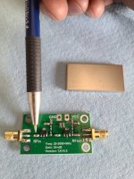
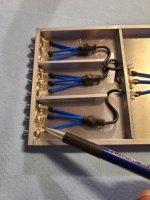
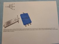
Also today for interest, I wanted to see how much temperature affects elements of these lengths and diameters. Picture 4 is a element cut to length in my basement shop which is a very constant 17 degrees Celsius. Picture 5 is the same element put in front of a heater I use to accelerate epoxy cure times. This element was hot when I measured it, at least 40 degrees Celsius. I then put the whole finished and antenna in one of my freezers for several hours while I was working the bender. I have a thermometer in it and it reads -20 Celsius. Picture 6 shows the same element being measured directly after coming out. Interesting results but don't know how much impact at this frequency it would have.

Thanks,
 

Attachments

  • 1.jpg
    1.jpg
    167.3 KB · Views: 6
  • 2.jpg
    2.jpg
    117.1 KB · Views: 3
  • 3.jpg
    3.jpg
    144.9 KB · Views: 4
  • 4.jpg
    4.jpg
    90.5 KB · Views: 5
  • 5.jpg
    5.jpg
    89.4 KB · Views: 3
  • 6.jpg
    6.jpg
    83.9 KB · Views: 5

VA3BBY

Member
Joined
Mar 29, 2023
Messages
45
I have a drawing done for the first attempt at a folded dipole and will start working on it today. I have my initial measurements from the Dipole online calculator, the results of this I think are free space and use very thin wire. I have changed dimensions for what I am working with.

As I mentioned I built a mechanical bender loosely based on some wire bender designs I looked at on Amazon. With my rule of thumb techniques ; ) I came up with picture 4, I had to make so it could be used in place. I started with some 1x2x1/2" bar stock I had on hand picture 2. The roller bearing is from a tired 1/4" shank wood router bit. The ID of this bearing fits an easily obtainable 10-32 machine screw (3/16"). This bearing really bends the 3.2mm element nicely around the centre shaft. I think picture 4 will show the press fit brass tube insert for soldering as well a the 4-32 hex head bolt to retain the element to the index mark on the bender shaft.

Picture 3 shows the test antenna I came up with, I cut this out of the very first one I made that also had a dipole. I abandoned this first antenna because of the LMR-195 coax I was using at the time and didn't think I could repeat the dipole dimensions by hand bending the wire around the first jig I made. Also, the 2 polarizations were not offset by the 1/4 wave I have now.

As I mentioned previously, there is good reason why commercial antennas use folded dipoles. I just didn't think I could repeat them, and still not convinced I can but will give it a good try.... I think is going to take some time as I will only vary the overall length by .5mm each attempt and the brass tubes will need to made and pressed into each one.

I sure miss my machine shop, the tools I am using now are nothing special and many would have.

Thanks
 

Attachments

  • 1.jpg
    1.jpg
    83.3 KB · Views: 5
  • 2.jpg
    2.jpg
    91.9 KB · Views: 5
  • 3.jpg
    3.jpg
    141.7 KB · Views: 4
  • 4.jpg
    4.jpg
    78.6 KB · Views: 4

VA3BBY

Member
Joined
Mar 29, 2023
Messages
45
Made a lot of dumb mistakes today like on the first element I cut, pressed in the brass soldering tubes and tinned them before I put it through the antenna. Not sure why I did that but it certainly wouldn't go through after the fact.

I had to change the CAD dwg a bit as after bending the element it had slight spring back which altered the arc dimension and well changed pretty much everything else... but it is dialed in now. I have also changed the offset a bit more to align with the centre conductor better. I don't quite understand the purpose of offsetting the feed point on boom mounted dipoles? Is it something to do with capacitance?

The first one works okay but high again in frequency, have done another drawing already to try in the morning. This first one is at 70 ohms see picture. If you phase two together at this does it bring you pretty close to 50 ohms?

On a side note, I watch a video on a generic LNA mod like the ones I have, see picture. By changing the first capacitor, pointed out by pencil in pic, to a ceramic band pass filter and by adding 1 or more gen purpose diodes like a 4001N to the positive input, it greatly enhances its effectiveness. I guess these 5v rated LNA's are way more happy around 3v which the diodes can provide plus some additional dc conditioning as well as making them run pretty much forever. At 5v the amplifier is overdriven. And the band pass filter helps get rid of some additional unwanted noise. Anyway I have some BFCN-1445+ on the way to replace the capacitor on the LNA's I have, I have plenty of gen purpose diodes on hand. I also found some nice shielding lids that fit these LNA's perfectly so once the mods are done I will solder them on. I need to sort out how much voltage drop I have from power supply to LNA's before I start adding diodes though.

I am going to put a small PVC box on the antenna frame at the base of each antenna. This will contain a LNA and the required phasing for the two polarizations of each antenna. It is too difficult to build the phasing into the coaxial lead coming from the back of the antenna boom, any alterations means cutting open the heat shrink or just cutting it off altogether and starting over. This has already been expensive for me..

I got the Idea of the LNA's from a video describing how the SKA in Australia works, inside each of these antennas is a cheap basic LNA as described in the video, there is nothing fancy about them at all. They use a separate saw filter but also need way wider bandwidth. The band pass I have coming are 1420 to 1470mhz and I guess they are similar to how they work as a capacitor. Perfect for me I think.

Thanks,
 

Attachments

  • 1.jpg
    1.jpg
    192.6 KB · Views: 3
  • 2.jpg
    2.jpg
    83 KB · Views: 4
  • 3.jpg
    3.jpg
    110.4 KB · Views: 3

VA3BBY

Member
Joined
Mar 29, 2023
Messages
45
This was every bit the challenge I was anticipating and a little bit more but I think I now have a good design.

My friend told me couple weekends ago that 109.5mm for the driven checked out on the HFSS software, I assumed for a straight element and gamma, there is a language barrier. I did not anticipate the end results of today, I started way shorter based on a calculator. As you can see in picture 3, folded dipoles are evil. They are either right or wrong, no gray area, no fudge factor and no rule of thumb apply to them. They can't be cut long and filed to tune and they have to be cut either side of the boom to de-solder so they can be removed so one can try again and again to get it on frequency. I would be skeptical of online calculators for this frequency, just my experience, and probably why there is disappointment in building at this range. .

Anyway, I think persistence has paid off. I will add 1mm to the length for the next full size antenna I build just because. But I believe this would work well as it is. Picture 4 shows todays final measurements. Prior to these pictures, I had only 1 phase on the boom otherwise the pile of cut in two dipoles would have been twice as big...

Picture 2 shows it is sitting at 38 some ohms, this is on the desired frequency(green dot) with the two phases Teed together which makes sense, as you can see it dips down lower off frequency to 35-36 this fluctuates with me moving around. This is where it should be, I say this loosely because its only from what I have read recently about folded dipoles. They usually are around 70-71 ohms each. Picture 1 shows what picture 2 is analyzing, the two phases Teed together.

I am happy, it has been a long road to get this far. Now I need to sort out how to bring this to the 50 ohms the radio would like to see at the back of the antenna. A 1/4 phasing coaxial loop at the dipole is not practical at this frequency. This only works on an engineers desk, out in the field is usually different ; ) . Then I need to phase them together as an array.

Thanks,
 

Attachments

  • 1.jpg
    1.jpg
    71.2 KB · Views: 4
  • 2.jpg
    2.jpg
    203.9 KB · Views: 5
  • 3.jpg
    3.jpg
    143.8 KB · Views: 5
  • 4.jpg
    4.jpg
    98.8 KB · Views: 4

VA3BBY

Member
Joined
Mar 29, 2023
Messages
45
Had the afternoon off so spent some time on a combiner idea I had. It was suggested I look into Wilkinson power divider/combiners a few times and I almost purchased 4 3-way units to cascade. Thankfully the sales person sent me a PDF spec sheet that was not listed on website. This showed a substantially higher insertion loss for my frequency of interest. It seems most of these readily available dividers are very wide banded.

So what I am attempting to do is combine 4 units into 1 case see pictures 1 and 2. This case is just tacked together right now so I can finalize the dimensions so the coax can be soldered in correctly. This is based on the Wilkinson design see picture 4 but using coaxial cable instead of PCB. I need to figure out the resistor value yet. For a 2-way Wilkinson this value is 100 ohms. I have not been able to find this information for a 3-way so I am going to start with 150ohm? see picture 3.

Thanks
 

Attachments

  • 1.jpg
    1.jpg
    127.1 KB · Views: 5
  • 2.jpg
    2.jpg
    110.2 KB · Views: 5
  • 3.jpg
    3.jpg
    90.3 KB · Views: 4
  • 4.jpg
    4.jpg
    90.2 KB · Views: 4

MUTNAV

Active Member
Premium Subscriber
Joined
Jul 27, 2018
Messages
1,086
Had the afternoon off so spent some time on a combiner idea I had. It was suggested I look into Wilkinson power divider/combiners a few times and I almost purchased 4 3-way units to cascade. Thankfully the sales person sent me a PDF spec sheet that was not listed on website. This showed a substantially higher insertion loss for my frequency of interest. It seems most of these readily available dividers are very wide banded.

So what I am attempting to do is combine 4 units into 1 case see pictures 1 and 2. This case is just tacked together right now so I can finalize the dimensions so the coax can be soldered in correctly. This is based on the Wilkinson design see picture 4 but using coaxial cable instead of PCB. I need to figure out the resistor value yet. For a 2-way Wilkinson this value is 100 ohms. I have not been able to find this information for a 3-way so I am going to start with 150ohm? see picture 3.

Thanks
Just to clarify, you're trying to use cascaded wilkinson power dividers???

Also, are you going to use low noise amplifiers at the feed-points for each antenna?
 

MUTNAV

Active Member
Premium Subscriber
Joined
Jul 27, 2018
Messages
1,086
The reason I mention this is that even at much lower frequencies (mw and HF) in something like a wullenweber array, they used low gain and adjustable amplifiers early on to overcome the losses of all of the lines and phasing / matching etc... that has to go on later.

Thanks
Joel
 

VA3BBY

Member
Joined
Mar 29, 2023
Messages
45
I don't know what you would call what I am building Joel. It is based on a Wilkinson but as anything designed to cram a lot into a small package and make it useful to a wide range, something is going to suffer like the insertion losses seen by Wilkinson dividers. If you look on-line, their bandwidth typically span 100's of Mhz, lots and lots. If you are lucky with your design frequency you will see .3 to .6 db loss if not you will see >5 dB. from one these off the self Wlkinson's. I was unlucky. I think you suggested a 12 port way back..

I think the issue with the Wilkinson design is the fact that the feed lines are just a trace on a PCB, now there are many types of substrates and some that help substantially with the losses of a strip line. And if you look inside one of these, some are just a squiggly trace with a resistor or two and some are filled with capacitors, resistors and inductors trying to compensate for something. Myself, I do not think there is a true substitute for coaxial line that offers the encompassed shielding as well as the capacitance required for modern radio equipment. Thus what I am trying here, just in less cable junctions to more the common coaxial phasing line setups. Remember, I do not have to be concerned about transmission wattage.

So what I am attempting is to start with the Wilkinson design but use coax to achieve this. Two things that are immediately in my favour are the lengths of coax I am dealing with as well as the size of it. This is hours of work for a specific frequency and I think, is why it is not done in industry. How would you stock a shelf with each desired frequency....

I cant really clarify what I am doing Joel beyond experimenting, as there is next to zero information available to a layman as myself. But I am trying really hard to provide information here to what does and does not work for anyone with a minimal to modest workshop.

Three posts back describe what I am doing with LNA's, I have received the band pass filters and am excited to see if this does work, these filters are the same size as a typical surface mount capacitor (tiny) . I am now sitting a my workbench and have a few hours to spend soldering this thing together.

Thanks
Bob
 

VA3BBY

Member
Joined
Mar 29, 2023
Messages
45
My friend in the Ukraine just told me what I am doing is called a 3-way planar wilkinson.
 

MUTNAV

Active Member
Premium Subscriber
Joined
Jul 27, 2018
Messages
1,086
I don't know what you would call what I am building Joel. It is based on a Wilkinson but as anything designed to cram a lot into a small package and make it useful to a wide range, something is going to suffer like the insertion losses seen by Wilkinson dividers. If you look on-line, their bandwidth typically span 100's of Mhz, lots and lots. If you are lucky with your design frequency you will see .3 to .6 db loss if not you will see >5 dB. from one these off the self Wlkinson's. I was unlucky. I think you suggested a 12 port way back..

I think the issue with the Wilkinson design is the fact that the feed lines are just a trace on a PCB, now there are many types of substrates and some that help substantially with the losses of a strip line. And if you look inside one of these, some are just a squiggly trace with a resistor or two and some are filled with capacitors, resistors and inductors trying to compensate for something. Myself, I do not think there is a true substitute for coaxial line that offers the encompassed shielding as well as the capacitance required for modern radio equipment. Thus what I am trying here, just in less cable junctions to more the common coaxial phasing line setups. Remember, I do not have to be concerned about transmission wattage.

So what I am attempting is to start with the Wilkinson design but use coax to achieve this. Two things that are immediately in my favour are the lengths of coax I am dealing with as well as the size of it. This is hours of work for a specific frequency and I think, is why it is not done in industry. How would you stock a shelf with each desired frequency....

I cant really clarify what I am doing Joel beyond experimenting, as there is next to zero information available to a layman as myself. But I am trying really hard to provide information here to what does and does not work for anyone with a minimal to modest workshop.

Three posts back describe what I am doing with LNA's, I have received the band pass filters and am excited to see if this does work, these filters are the same size as a typical surface mount capacitor (tiny) . I am now sitting a my workbench and have a few hours to spend soldering this thing together.

Thanks
Bob
Gotcha ( I think) I was just wondering what the problem was with wide-band combiners (the loss shouldn't be a problem with a amp ahead of each antenna).


Most of the wilkinson stuff I read was for transmitting (combining multiple amplifiers), and its big effect was that the loss of any amplifier would just show up as a reduction of power, not the loss of the entire set of amplifiers, and any mismatches would show up as resistors heating up. But they only work as intended if all of the impedance (source, load, and line) are as designed.

Great experimenting though. It makes me recall some other astronomers, one had his data messed with when the internet was just becoming popular, and ended up in front of congress as an expert in computer hacking, the other would climb a mountain on weekends when the sky was supposed to be clear, to get a good view of the stars, the weather forecasts were so bad he ended up doing his own, and becoming a weather forecaster.


Thanks
Joel
 

prcguy

Member
Joined
Jun 30, 2006
Messages
15,349
Location
So Cal - Richardson, TX - Tewksbury, MA
So a very interesting factoid, as I mentioned earlier, I trimmed the phasing stubs 9mm. Basically cut off the soldering shown in the previous picture hanging out the back of the antenna boom. . I did this because that is what I have my coax stripper set at and thought I would just cut back to un altered coax and start over. That 9mm shifted the centre frequency 44Mhz. More than 20 more than I would have been happy with. Crazy. See picture and compare with previous, just wow. What's a 1/4 inch, a little more than 6mm...
The change in frequency when cutting coax is about the same as the difference in cutting an antenna. A 9mm change at 70cm should only move you about 15MHz so I would question your 44MHz result.
 

VA3BBY

Member
Joined
Mar 29, 2023
Messages
45
I will become a book writer, my first book will be "1001 wrong ways on how to build a Yagi Array for Radio Astronomy."

After taking this combiner apart I measured each of the segments and they all come up as less than 1.8:1 swr @ 1420.5mhz. I have not added the required resistors for this measurement. My friend has told me that I was incorrect with my choice of the blue coax @ 1/4 wave 75ohm. It should be 1/4 wave 100 ohm. and my resistor value should be 76.9 ohms.

As I have neither, I will finish putting this together as a curiosity.
 

prcguy

Member
Joined
Jun 30, 2006
Messages
15,349
Location
So Cal - Richardson, TX - Tewksbury, MA
Actually reading all the posts it seems you are building all this for hydrogen line reception. Why not buy used 12 way dividers off eBay? They come up all the time cheap like $75 or less and I don’t think you can make one that will equal the specs, especially insertion loss, port to port isolation and equal phase through all ports. Here is an expensive one at $120 but they will show up much cheaper.


Also, why so many LNAs? If you combine all the antennas with low loss coax into one LNA you will only loose maybe a few tenths of a dB noise figure compared to LNAs at every antenna and different LNAs can have different phase shifts going through them which will cause problems combining downstream.
 

VA3BBY

Member
Joined
Mar 29, 2023
Messages
45
It actually should be 60mhz for 9mm at this frequency range when I do the math, I made an error in design somewhere way back then, sorry my bad... thanks for your comment and have a good day!
 

VA3BBY

Member
Joined
Mar 29, 2023
Messages
45
Joel, I have been thinking about a recent comment you made, I should have said something earlier but was busy with my project. I think you and I are somewhat on the same page.

"Gotcha ( I think) I was just wondering what the problem was with wide-band combiners (the loss shouldn't be a problem with a amp ahead of each antenna)."

Why, when you can do a little better? Or try too. Why not try to do a little better than what is readily available? As I have mentioned before and to the effect , I realize what I am building will have a tiny wee tiny of the capabilities for radio astronomy that is required. The purpose of my hobby is to build something to the best it can be. Whether it be using off the self components or something that has to be made to fit a particular requirement.

And to answer pcrguy comment, his is not an ease of convenience or money saving endeavor, plus, you should take the time to investigate the specifications of such inexpensive components before posting. They are that way for a reason.

This is just a hobby, and I am not out to prove anything but rather help someone with a similar interest.

Thanks,
Bob
 

prcguy

Member
Joined
Jun 30, 2006
Messages
15,349
Location
So Cal - Richardson, TX - Tewksbury, MA
Joel, I have been thinking about a recent comment you made, I should have said something earlier but was busy with my project. I think you and I are somewhat on the same page.

"Gotcha ( I think) I was just wondering what the problem was with wide-band combiners (the loss shouldn't be a problem with a amp ahead of each antenna)."

Why, when you can do a little better? Or try too. Why not try to do a little better than what is readily available? As I have mentioned before and to the effect , I realize what I am building will have a tiny wee tiny of the capabilities for radio astronomy that is required. The purpose of my hobby is to build something to the best it can be. Whether it be using off the self components or something that has to be made to fit a particular requirement.

And to answer pcrguy comment, his is not an ease of convenience or money saving endeavor, plus, you should take the time to investigate the specifications of such inexpensive components before posting. They are that way for a reason.

This is just a hobby, and I am not out to prove anything but rather help someone with a similar interest.

Thanks,
Bob
I have a 40 year career specifying microwave components for the best system performance and a very good track record doing so. In the case of the divider I posted anyone would have difficulty getting close to the same specs let alone surpass them in a home lab.
 

VA3BBY

Member
Joined
Mar 29, 2023
Messages
45
Good for you pcrguy, you are obviously better than me and have the knowledge of the world and better than most. . And you are
obviously very good at deterring anyone from bettering their knowledge through experimentation and self learning.

Thank you for your comment,
 

VA3BBY

Member
Joined
Mar 29, 2023
Messages
45
Actually, you know what pcrguy, i am just going to stop posting altogether. I do not need your BS and I am not obilgated to share my findings here as much work as it is.

good bye,
 

prcguy

Member
Joined
Jun 30, 2006
Messages
15,349
Location
So Cal - Richardson, TX - Tewksbury, MA
Good for you pcrguy, you are obviously better than me and have the knowledge of the world and better than most. . And you are
obviously very good at deterring anyone from bettering their knowledge through experimentation and self learning.

Thank you for your comment,
I asked a few questions and made a few suggestions. Is that a reason for you to berate me? I wish you all the luck with your project.
 
Status
Not open for further replies.
Top