12 Yagi array

Status
Not open for further replies.

MUTNAV

Active Member
Premium Subscriber
Joined
Jul 27, 2018
Messages
1,297
Lots of great points and questions....

The first is that the velocity factor is a rough planning factor, it varies a lot, from roll to roll and according to some, foot by foot.

One of your points did open an old can of worms in my head.... some people really like measuring things based on resonant frequency, I have to assume because they want to control SWR or dont have better test equipment for other tests... The other way of measuring is "phasing" ie 90 degrees at 1.5 Ghz or something, this is good if you want to put something into quadrature to make a measurement.... The best (to me) idea is to use the actual time delay of a line, this is how they (them?) make wideband phased arrays, the swr and everything else will be off, but wide-banding things is sometimes more important... If you look at the wullenweber description, it was supposed to work from 1 Mhz to 30 Mhz with very high accuracy.... measuring and cutting things for SWR or Phase delay just wouldn't work (too broadband).

The part about your post that will get most people annoyed, is that after measuring the cable with the connectors on, and you need to cut it, you have to take the connector off, cut it, and (in my case) re-install the same connector, if you are using N connectors there is a rubber gasket that breaks when you put it on the first time, so you loose a little waterproofing when it's redone, but it would be ridiculous
s to use a new connector every time (especially if you get to more than two cuts per cable)

There's actually a formula to use for figuring out how much the second cut should be, I just don't remember it though.


The article for the 12 foot stressed dish is in the ARRL handbook PDF I included in a previous post (post #9) the article is page 19-35. if you like all of the space communications data in it, becoming an ARRL member might give a lot more access to "interesting" stuff

for the wullenweber array


Thanks
Joel
 
Last edited:

paulears

Member
Joined
Oct 14, 2015
Messages
905
Location
Lowestoft - UK
I’m reading this with interest. I do know that I’d not put too much emphasis in this project in decimal points when the magnitude of errors in the construction is far more important. In the lower bands, tolerances when cutting are much more experiment friendly, but above the GHz barrier, 2mm is considered a very large measurement, and maybe 2.2mm means a range of construction accuracy is important. Years ago, I built one 1.3GHz antenna and discovered mechanics are vital. Sag, in a thinner boom reduced the gain significantly as the weight of the feeder made it banana shaped. A commercial repurposed phasing harness worked great, but then again the achieved gain never met the design spec figures because toe in and toe out of the booms spoiled it by even small movements. I discovered my soldering, perfectly good enough for making things on pcbs and connectors, was not good enough for microwaves, and I also discovered the type on the outer sheath often meant little when the cable construction was less good. I just never learned the skills to put on small connectors properly first time, and second time usually meant flawed.

I’m very impressed with the work being put in here. I know for me, this would be. A jump far too far for me. I’d struggle with stacking or baying two!
 

merlin

Active Member
Joined
Jul 3, 2003
Messages
3,235
Location
DN32su
I think the reason information is so hard to come by is the fact that such VHF array's
go back to 1945 radar installations.
The only such installation I have seen in modern times is for amateur EME work.
For myself, I had an 11 element cross Yagi with quite a cluster of phasing links and relays.
The Yagi was mounted to a heavy duty pan/tilt for tracking satellites.
2 feeds (H/V) into a weatherproof box that contained the phasing setup and preamp.
Phasing is not overly critical at VHF but above 500 Mhz it gets rather touchy.
I don't see why one could not stack any number of such antennas together,
but in numbers you wont be very steerable.
Cheers
 

merlin

Active Member
Joined
Jul 3, 2003
Messages
3,235
Location
DN32su
@ VA3BBY:
Anyway, I think the other changes I have made were very positive, going from 2.4mm reflector and driven to 3.17mm and going from .100 aluminum sheet for the shorting bar to .125 bar. I went back to a solid rod and to a t-match from gamma with help from a new friends calculator in the Ukraine. See attached pictures and result. Right now I am making the full set of T-match's 2mm longer as this shifts the capacitance with frequency.

When you go to larger diameters, the bandwidth of the antenna increases.
Lengths should be left untouched. You can see a change with T-match with a VNA.
The reactance will change significantly.
 

MUTNAV

Active Member
Premium Subscriber
Joined
Jul 27, 2018
Messages
1,297
I’m reading this with interest. I do know that I’d not put too much emphasis in this project in decimal points when the magnitude of errors in the construction is far more important. In the lower bands, tolerances when cutting are much more experiment friendly, but above the GHz barrier, 2mm is considered a very large measurement, and maybe 2.2mm means a range of construction accuracy is important. Years ago, I built one 1.3GHz antenna and discovered mechanics are vital. Sag, in a thinner boom reduced the gain significantly as the weight of the feeder made it banana shaped. A commercial repurposed phasing harness worked great, but then again the achieved gain never met the design spec figures because toe in and toe out of the booms spoiled it by even small movements. I discovered my soldering, perfectly good enough for making things on pcbs and connectors, was not good enough for microwaves, and I also discovered the type on the outer sheath often meant little when the cable construction was less good. I just never learned the skills to put on small connectors properly first time, and second time usually meant flawed.

I’m very impressed with the work being put in here. I know for me, this would be. A jump far too far for me. I’d struggle with stacking or baying two!
I'm also impressed with the work and enthusiasm of whats being done...

Thanks
Joel
 

VA3BBY

Member
Joined
Mar 29, 2023
Messages
45
Thank you for your advise and comments folks,
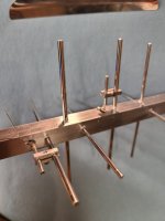
Success today, first antenna finished. I cut a rod for each of the different elements to use to get them perfectly centred. I ended up peening the the elements in place. I set up a test piece for the tig welder with 6 elements in it to see how it would go. Melted every one of them off .... Was a good idea in theory.

Have attached some pictures of the results. Although this far has been very time consuming, I think the hard part is yet to come...
 

Attachments

  • 20230507_182740.jpg
    20230507_182740.jpg
    173.1 KB · Views: 14
  • 20230507_182746.jpg
    20230507_182746.jpg
    167.5 KB · Views: 8
  • 20230507_092629.jpg
    20230507_092629.jpg
    91.4 KB · Views: 14
  • 20230507_174024.jpg
    20230507_174024.jpg
    43 KB · Views: 14
  • 20230507_182724.jpg
    20230507_182724.jpg
    82.5 KB · Views: 14

MUTNAV

Active Member
Premium Subscriber
Joined
Jul 27, 2018
Messages
1,297
Found it.... A simple schematic for a vector voltmeter... In this PDF page 8-33, its probably worth reading the whole book, especially the chapter it's in. At the frequencies you're talking about you will have to think a lot about lead length and component selection. or just use a lower frequency and scale the results. The page before even shows the use of an o'scope to measure phasing (although not for your application)


https://ia801501.us.archive.org/3/items/the-arrl-antenna-book-the-ultimate-reference-for-amateur-radio-antennas/The_ARRL_Antenna_Book_The_Ultimate_Reference_for_Amateur_Radio_Antennas.pdf
Thanks
Joel
 

VA3BBY

Member
Joined
Mar 29, 2023
Messages
45
Thank you Joel, But I do not see the VVM . It talks about antenna switching and a current probe. You had provided this book link previously, I looked through it then too. To be honest much in this book is beyond my lack of electrical engineering skills mostly because of the formulas involved, I have not been educated for that. Even the diagram on page 8-33 that shows the current probe and the wraps around the core with the coax to it. the diagram shows no resistor but says one needs to be added. This is the type of thing that gets very fuzzy for me to a point where I would not be able to build it. I am sure with the proper education and people with such would say "yeah, duh, the resistor just goes there, everyone knows that.."

As I mentioned before, I am very capable of building things to exacting tolerances as long as I am given the detailed plans to do so. Trying to follow some of this stuff presented in books where it is just assumed that the person reading it has an advanced enough education to fill in the blanks and or understand complex equations is well beyond my scope. I would have to go back to school for years to just understand it.

I really do appreciate you taking the time to forward this information to me and would really like and need the capability to verify the complex phasing adventure I am about to embark on. I do understand the requirement and its importance, just need to figure out how to do so with my humble workshop.

Thanks,
Bob
 

VA3BBY

Member
Joined
Mar 29, 2023
Messages
45
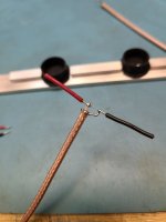
Here is some serious boom sag and sideways action combined, I think this this one is 60 feet long for EME and is interesting of how they are correcting it. I do have a bouncing problem with mine as it is end of boom mounted. If I bump the antenna it will bob up and down for about 10 seconds. I have thought about plugging the coax end and filling about 1/3 its length with West System epoxy to stiffen it. But once this is done there is no turning back on doing anything with the coax later. I have search for dampening such an oscillation but have not found anything yet. The antenna has no visible sag and is very light - 380 grams (13.7 OZ) complete I weighed it yesterday with a postal scale and 1600mm (5' - 3") overall length.

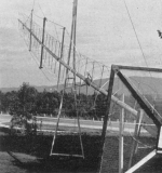
This is interesting article I came across. I think the radar arrays mentioned would be similar to some of the arrays here.
The first Amateur Lunar tests & contacts |2nd part: 1966-1976

Thanks,
Bob
 

Attachments

  • k1kkp_1966.png
    k1kkp_1966.png
    189.8 KB · Views: 8
Last edited:
MUTNAV

Active Member
Premium Subscriber
Joined
Jul 27, 2018
Messages
1,297
Thank you Joel, But I do not see the VVM . It talks about antenna switching and a current probe. You had provided this book link previously, I looked through it then too. To be honest much in this book is beyond my lack of electrical engineering skills mostly because of the formulas involved, I have not been educated for that. Even the diagram on page 8-33 that shows the current probe and the wraps around the core with the coax to it. the diagram shows no resistor but says one needs to be added. This is the type of thing that gets very fuzzy for me to a point where I would not be able to build it. I am sure with the proper education and people with such would say "yeah, duh, the resistor just goes there, everyone knows that.."

As I mentioned before, I am very capable of building things to exacting tolerances as long as I am given the detailed plans to do so. Trying to follow some of this stuff presented in books where it is just assumed that the person reading it has an advanced enough education to fill in the blanks and or understand complex equations is well beyond my scope. I would have to go back to school for years to just understand it.

I really do appreciate you taking the time to forward this information to me and would really like and need the capability to verify the complex phasing adventure I am about to embark on. I do understand the requirement and its importance, just need to figure out how to do so with my humble workshop.

Thanks,
Bob
Figure 32 is the vector voltmeter, it wouldn't be calibrated... I wouldn't even have gotten as far as you with all of the precision cuts.

Thanks
Joel
 

VA3BBY

Member
Joined
Mar 29, 2023
Messages
45
That is my lack of education showing, I did not know a Quadrature test circuit and vector voltmeter are the same. I could build this circuit but have no idea what T1 is - 7 trifi lar turns on an Amidon FT-37-43, -75, -77, or equivalent ferrite toroid core is and would not be able to build this, its like wraps where on what part kinda of thing... and what to you do with the hook up points?

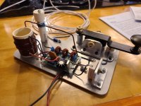
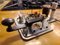
Here is an example of my education, I do not remember where the schematic's for this came from but the wraps on coil forms and it's taps as well as toroid's was very well explained. The finished layout was left to interpretation as it was a schematic but placement seemed logical. My son and I built two of these together downstairs (see pictures). My sons is a little rougher around the edges but he was 15 at the time and his works just as well as mine. We built the transmitter and keyer as a unit because we thought it would look cool and to me this is just as much art. They are about 50mw and have a very clean signal verified with my scope. I could verify this because W2AEW is an excellent teacher with his videos and every time I need to use my scope for something I will check him out. Otherwise I would not be able to use it.

Anyway, I have a well stocked drawer full of components and perforated PCB's as well as breadboards, the keyer parts all came from the hardware store and I always have aluminium shapes and plate on hand as my son was learning to TIG after I taught him to MIG.

This was a fun project for the two of us. Just as this antenna array is a fun project for me.

These transmitters are all scratch built and work well at 3.685mhz. I just looked at many keyer pictures and figure a way to make one with what I could get my hands on in this tiny town. The only way I could do this is because there was nothing left to question when I came to the schematics. The person that offered this up, I wish I could remember, should be writing a book " Electronics for Dummies"

Thanks,
Bob
 

Attachments

  • 20230508_195630.jpg
    20230508_195630.jpg
    149.4 KB · Views: 3
  • 20230508_195900.jpg
    20230508_195900.jpg
    134.9 KB · Views: 3
  • 20230508_200114.jpg
    20230508_200114.jpg
    133.4 KB · Views: 3

MUTNAV

Active Member
Premium Subscriber
Joined
Jul 27, 2018
Messages
1,297
That is my lack of education showing, I did not know a Quadrature test circuit and vector voltmeter are the same. I could build this circuit but have no idea what T1 is - 7 trifi lar turns on an Amidon FT-37-43, -75, -77, or equivalent ferrite toroid core is and would not be able to build this, its like wraps where on what part kinda of thing... and what to you do with the hook up points?

Here is an example of my education, I do not remember where the schematic's for this came from but the wraps on coil forms and it's taps as well as toroid's was very well explained. The finished layout was left to interpretation as it was a schematic but placement seemed logical. My son and I built two of these together downstairs (see pictures). My sons is a little rougher around the edges but he was 15 at the time and his works just as well as mine. We built the transmitter and keyer as a unit because we thought it would look cool and to me this is just as much art. They are about 50mw and have a very clean signal verified with my scope. I could verify this because W2AEW is an excellent teacher with his videos and every time I need to use my scope for something I will check him out. Otherwise I would not be able to use it.

Anyway, I have a well stocked drawer full of components and perforated PCB's as well as breadboards, the keyer parts all came from the hardware store and I always have aluminium shapes and plate on hand as my son was learning to TIG after I taught him to MIG.

This was a fun project for the two of us. Just as this antenna array is a fun project for me.

These transmitters are all scratch built and work well at 3.685mhz. I just looked at many keyer pictures and figure a way to make one with what I could get my hands on in this tiny town. The only way I could do this is because there was nothing left to question when I came to the schematics. The person that offered this up, I wish I could remember, should be writing a book " Electronics for Dummies"

Thanks,
Bob
The circuit would have the effect of a vector voltmeter, it could tell a certain amount of info, but not like a real one (even a real one like in the pictures, would only go to 1 Ghz).

Your transmitters look good and fun, what a great project for a kid and dad to do together.

Thanks
Joel.
 

VA3BBY

Member
Joined
Mar 29, 2023
Messages
45
What a pleasant discovery over morning coffee. You folks must check this out. I am certainly going thank this individual for taking the time to post this wonderful information.


VA3BBY

Member
Joined
Mar 29, 2023
Messages
45
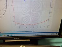
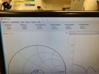
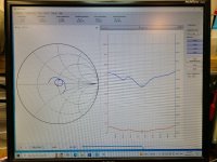
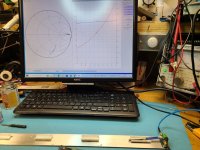
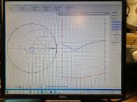
I changed the design of the shorting bars a bit on the antenna I have been working on. The first design deformed too much when crimped (see pictures 1 and 2) and I was worried about corrosion. I cut a slot in the new and it crimped way better with even clamping. I also spent a little more time tuning. See results in picture A.

I ordered a MAX2870 23.5‑6000Mhz RF Signal Source and it had arrived. I thought this would be a good way to test this antenna as I am not sure or confident of my matching methods. As I have said previously, “ I have found many ways on how not to match an antenna”

Hopefully someone can answer these three questions as I do not know if the results are good or bad?

Question 1

I have the signal generator set up 20 feet from the antenna. The conditions here are not ideal for testing but probably pretty close to a commercial antenna lab. I have the antenna in in my office screwed to the window sill pointed out the door across the living room to the signal generator sitting on the back of the sofa. Too much metal stuff downstairs so figured this was better and more scientific….

The signal generator is set at its lowest power setting of 189 uw (micro watts) according to a Youtube review of this thing. It actually has a really clean signal at this frequency.

I have the RF Output of the signal generator terminated with a 50 ohm – 6Ghz 1/4 watt load. So I am not sure how any signal is coming out at all?

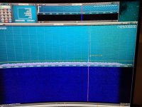
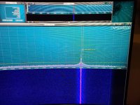
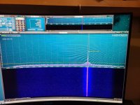
I have taken 3 pictures of the signal received by the antenna. Personally I was expecting a whole lot more signal strength with source so close.

Picture 3 is the random wire antenna which is 2 feet closer (18 feet) on input B of receiver showing peak signal strength -114.3db. This random wire just runs along the ceiling of office and down door jamb to receiver.

Picture 4 is the Yagi antenna on input A of receiver at 1425Mhz showing peak signal strength -89.4db.

Picture 5 is the Yagi antenna on input A of receiver at 1420.405Mhz showing peak signal strength -86.3db

The background noise is peaking at -135db with the receiver RF Gain set to minimum.

Are these results good or bad?, I really do not know and am just starting to understand dBm.

Question 2

Is this antenna showing good results from the VNA software (picture A)? All I understand of the numbers at this point are the Ohms and reflected power, Also, I do not understand why this antenna match’s with a solid wire T-match.

Question 3

This antenna has the X elements offset by 1/4 wavelength. I originally cut the two 75ohm coax feeds at 7/4 wavelength. When they came out the back of the antenna boom the one coax was not quite long enough to make an easy loop to heat shrink (there is a picture of this previously somewhere here) so I cut 1/4 wave off it to make both coax’s equal length. This antenna has 1- 75ohm feed of 7/4wave and 1- 75ohm feed of 6/4wave combined at a 50ohm female connector. Why does this antenna match? Is it still circular polarized? If not what is it besides an abomination?

Because I am so unsure of the answers to my questions above I have built a jig for another design of a T-match to test. This time incorporating a capacitor tube and 9/4wave feeds so one can be looped nicely and heat shrinked. I have built a pair of these today and the forming jig worked well. I should have another boom drilled tomorrow morning and built so I can compare antenna match’s maybe Sunday.

Which makes me think of one more question, would an antenna lose signal strength going from a solid wire T-match to a capacitive T-match??

If anyone has some thoughts on the above they would be greatly appreciated.

I did make today the “Measuring a 1/4 λ line as a stub, performed by PA2CV, Alex:” from the link I posted previous and tried to be a little more precise with the construction, it does work. I will post pictures tomorrow or Sunday of my progress.

Oh ya, and my rottie is lying on the sofa as well, so that's just a ginormous grounding source or something to boot..

Thanks,
 

Attachments

  • A.jpg
    A.jpg
    152.7 KB · Views: 4
  • 1.jpg
    1.jpg
    61.9 KB · Views: 6
  • 2.jpg
    2.jpg
    64.9 KB · Views: 5
  • 3.jpg
    3.jpg
    193.2 KB · Views: 4
  • 4.jpg
    4.jpg
    214.9 KB · Views: 2
  • 5.jpg
    5.jpg
    173 KB · Views: 3
Last edited:
VA3BBY

Member
Joined
Mar 29, 2023
Messages
45
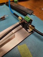
A lot has happened between last weekend and now. I was both disappointed and thankful of the lack of response to my last questions. The disappointment was lack of information from anyone here making this process easier. The thankful part was no-one here blowing smoke. I will say this, it is an expensive endeavour designing at this frequency and hope my sharing will benefit someone and am starting to think due to the lack of response, I am breaking ground here.

So, last weekend was full of mistakes to the point where I went through 10m of rg179 coax to the garbage can trying to match this antenna with the said Gamma T match design idea and its mould ( picture 1A and B) should have just stayed an idea, what disappointing results. I am quite sure the results of this experiment could not be any further from something good if one tried to achieve that... LoL

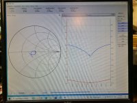
To answer my previous post question 1 while talking to myself , the results are not good. And It cant be because of question 2 and 3. The way the T-match is set up with the 7/4 and 6/4 wavelength coax's, it is forcing this antenna to match at other than it's resonance frequency.

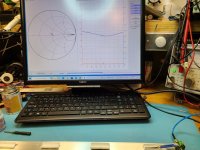
I had found this out late last weekend trying to make the calculated Gamma match work with as many wasted lengths of RG174 50 ohm coax. Late Sunday night I had the brain wave to widen the frequency span of the VNA by a lot. Actually from 1400mhz to 1450mhz to 1300mhz to 1500mhz.

Doing this enlightened me to the fact that this antenna was actually resonating at 1470mhz. picture 2A There is a combination of a few things going on here. 1, I am not sure that EZNEC software is so accurate in these higher frequencies and 2, boom correction calculators are not so accurate at these frequencies also. Although I must mention that my boom size of 12.7mm (1/2 inch) square was cautioned as being too large for this frequency in some calculators by 1mm. From experience, 1mm is a big difference at this frequency and I mean from a no-go to a-go . But on the same hand going less than 1/2 inch is just not practical for a boom.

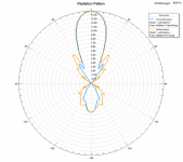
I had ask my friend in the Ukraine for advise. She willingly spent some time to run my design through her HFSS software. If you are not familiar with software suite, I believe the starting license fees for this are in the 40K range. Although she had to simplify my design somewhat to keep HFSS from consuming more than her allocated 16GB of ram she confirmed this antenna was resonating at a much higher frequency than designed and also 3dBi gain lower than EZNEC. She did say some of this is due to the simplification process.

So, in other words, I have yet again, made 400 some odd mistakes in cutting elements... live and learn again. One would think I should be disappointed. Actually I am not. This is a brain exercising experience in which, when I actually get this array to work, it will be very rewarding. Both, my friend and my calculations show the elements being too short by about 4.5mm and we have come up with the same results but by different means. Her's by 4.454mm and mine by 4.5mm.

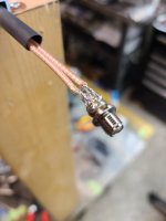
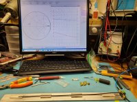
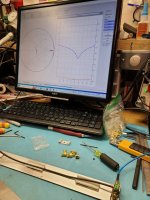
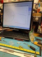
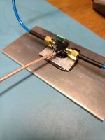
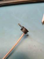
I made two stub coax connectors for VNA sampling (pictures 3a , 3b). The first was from the PA2CV design but I found that soldering the coax ends was both inconvenient and depending on where the solder joint was made could vary the results, only by a little but did vary. The second stub connector I made used a mini terminal, this way I could butt the insulation of centre conductor up to the clamping point of the mini terminal for repeatability. I am positive this will be <.25mm variance with this method. I have proved this with pictures 4a to 4d.

I think this will answer your comment Joel of "One of your points did open an old can of worms in my head.... some people really like measuring things based on resonant frequency," I think you almost answered your own question yourself Joel with a following comment "The first is that the velocity factor is a rough planning factor, it varies a lot, from roll to roll and according to some, foot by foot." I think the old hands at this did realized that coax varied foot by foot and the only way to measure this variance was by resonance. To be honest, I also found this out today. I have attached pictures (4 a to d) that show the trimming of two pieces of coax by resonance rather than by length or time delay. At resonance one piece is 359mm for 9/4 wavelength and the other is 357.8mm for the same and this was done with a consecutive piece from same roll of coax. . This trimming was done with my reasonably high quality flush cutter and I kid you not, I was just taking shavings off the end of the coax. This is RG174 50 ohm not the 75. Based on the first piece of coax I cut the second one to 370mm (about 10mm longer) and trimmed to length with success. I do not think it is a requirement to make coax at resonance when you are trying to make each piece the same electrical length for phasing but it sure makes sense to me to compensate for varying manufacturing processes and or machine variances due to a wide number of plant conditions.

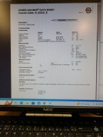
I have attached a spec sheet of this coax picture (5A), I do not think you could obtain any better. In fact the spec sheet modestly claims .66% VF. At this frequency it worked out to be .7557% as verified and clearly shows this coax was rated using a much higher test frequency than usual. Justfully so, considering it was $10/m for RG174 here in Canada... I also purchased the same coax but in 75 ohm for the1/4 phasing of antennas together.

That was another mistake last weekend, I used 9/4 wave RG179 75 ohm feed to try and match the T-match. This is good in theory, odd-wavelength for balun's but what (they, the other guy's) don't tell you. If you make an error in that feed it is multiplied 9 times.. I also found this out the hard way, Lol. So it is best to go with two 1/4 wavelength 75ohm coax in parallel where possible for phasing.

This really reinforces Merlin's comments , and I mean really, basically stating there is no forgiveness in phasing. And I can certainly appreciate why this endeavor would not be for the timid, this is exacting and expensive if you want it to perform.

I do know, understand and realize, that the scale of my project is so incredibly small (puny) to produce any really tangible results or resolution for radio astronomy. This is not the purpose of my exercise, but rather, to build this array to work at it's designed frequency to the best of my ability. While sharing some insight to you folks who have a similar interest. There is no information on the internet for this Yagi Radio Astronomy design although it is a reasonable antenna to build and who cares beyond the point of you built this yourself. And again, it will look cool!

In my case, even if I only get a little extra noise when pointed at Cygnus A it would sure put a smile on my face. This is just a ginormous mathematical and tedious building project for me and with its many challenges it is sure keeping me very engaged and occupied. A welcome mind exercise.

And I have changed the shorting bars again, I am going to drill and tap them with 2-56 for better clamping and adjustment. stay tuned.

Thanks,
 

Attachments

  • 4d.jpg
    4d.jpg
    181.9 KB · Views: 3
  • 4c.jpg
    4c.jpg
    185.1 KB · Views: 1
  • 4b.jpg
    4b.jpg
    107.8 KB · Views: 2
  • 4a.jpg
    4a.jpg
    116.3 KB · Views: 3
  • 5a.jpg
    5a.jpg
    81.5 KB · Views: 3
  • 3a.jpg
    3a.jpg
    69.4 KB · Views: 3
  • 2a.jpg
    2a.jpg
    145.2 KB · Views: 1
  • 1b.jpg
    1b.jpg
    32 KB · Views: 1
  • 1a.jpg
    1a.jpg
    40.9 KB · Views: 1
  • 3b.jpg
    3b.jpg
    76.5 KB · Views: 4

MUTNAV

Active Member
Premium Subscriber
Joined
Jul 27, 2018
Messages
1,297
A lot has happened between last weekend and now. I was both disappointed and thankful of the lack of response to my last questions. The disappointment was lack of information from anyone here making this process easier. The thankful part was no-one here blowing smoke. I will say this, it is an expensive endeavour designing at this frequency and hope my sharing will benefit someone and am starting to think due to the lack of response, I am breaking ground here.

So, last weekend was full of mistakes to the point where I went through 10m of rg179 coax to the garbage can trying to match this antenna with the said Gamma T match design idea and its mould ( picture 1A and B) should have just stayed an idea, what disappointing results. I am quite sure the results of this experiment could not be any further from something good if one tried to achieve that... LoL

To answer my previous post question 1 while talking to myself , the results are not good. And It cant be because of question 2 and 3. The way the T-match is set up with the 7/4 and 6/4 wavelength coax's, it is forcing this antenna to match at other than it's resonance frequency.

I had found this out late last weekend trying to make the calculated Gamma match work with as many wasted lengths of RG174 50 ohm coax. Late Sunday night I had the brain wave to widen the frequency span of the VNA by a lot. Actually from 1400mhz to 1450mhz to 1300mhz to 1500mhz.

Doing this enlightened me to the fact that this antenna was actually resonating at 1470mhz. picture 2A There is a combination of a few things going on here. 1, I am not sure that EZNEC software is so accurate in these higher frequencies and 2, boom correction calculators are not so accurate at these frequencies also. Although I must mention that my boom size of 12.7mm (1/2 inch) square was cautioned as being too large for this frequency in some calculators by 1mm. From experience, 1mm is a big difference at this frequency and I mean from a no-go to a-go . But on the same hand going less than 1/2 inch is just not practical for a boom.

I had ask my friend in the Ukraine for advise. She willingly spent some time to run my design through her HFSS software. If you are not familiar with software suite, I believe the starting license fees for this are in the 40K range. Although she had to simplify my design somewhat to keep HFSS from consuming more than her allocated 16GB of ram she confirmed this antenna was resonating at a much higher frequency than designed and also 3dBi gain lower than EZNEC. She did say some of this is due to the simplification process.

So, in other words, I have yet again, made 400 some odd mistakes in cutting elements... live and learn again. One would think I should be disappointed. Actually I am not. This is a brain exercising experience in which, when I actually get this array to work, it will be very rewarding. Both, my friend and my calculations show the elements being too short by about 4.5mm and we have come up with the same results but by different means. Her's by 4.454mm and mine by 4.5mm.

I made two stub coax connectors for VNA sampling (pictures 3a , 3b). The first was from the PA2CV design but I found that soldering the coax ends was both inconvenient and depending on where the solder joint was made could vary the results, only by a little but did vary. The second stub connector I made used a mini terminal, this way I could butt the insulation of centre conductor up to the clamping point of the mini terminal for repeatability. I am positive this will be <.25mm variance with this method. I have proved this with pictures 4a to 4d.

I think this will answer your comment Joel of "One of your points did open an old can of worms in my head.... some people really like measuring things based on resonant frequency," I think you almost answered your own question yourself Joel with a following comment "The first is that the velocity factor is a rough planning factor, it varies a lot, from roll to roll and according to some, foot by foot." I think the old hands at this did realized that coax varied foot by foot and the only way to measure this variance was by resonance. To be honest, I also found this out today. I have attached pictures (4 a to d) that show the trimming of two pieces of coax by resonance rather than by length or time delay. At resonance one piece is 359mm for 9/4 wavelength and the other is 357.8mm for the same and this was done with a consecutive piece from same roll of coax. . This trimming was done with my reasonably high quality flush cutter and I kid you not, I was just taking shavings off the end of the coax. This is RG174 50 ohm not the 75. Based on the first piece of coax I cut the second one to 370mm (about 10mm longer) and trimmed to length with success. I do not think it is a requirement to make coax at resonance when you are trying to make each piece the same electrical length for phasing but it sure makes sense to me to compensate for varying manufacturing processes and or machine variances due to a wide number of plant conditions.

I have attached a spec sheet of this coax picture (5A), I do not think you could obtain any better. In fact the spec sheet modestly claims .66% VF. At this frequency it worked out to be .7557% as verified and clearly shows this coax was rated using a much higher test frequency than usual. Justfully so, considering it was $10/m for RG174 here in Canada... I also purchased the same coax but in 75 ohm for the1/4 phasing of antennas together.

That was another mistake last weekend, I used 9/4 wave RG179 75 ohm feed to try and match the T-match. This is good in theory, odd-wavelength for balun's but what (they, the other guy's) don't tell you. If you make an error in that feed it is multiplied 9 times.. I also found this out the hard way, Lol. So it is best to go with two 1/4 wavelength 75ohm coax in parallel where possible for phasing.

This really reinforces Merlin's comments , and I mean really, basically stating there is no forgiveness in phasing. And I can certainly appreciate why this endeavor would not be for the timid, this is exacting and expensive if you want it to perform.

I do know, understand and realize, that the scale of my project is so incredibly small (puny) to produce any really tangible results or resolution for radio astronomy. This is not the purpose of my exercise, but rather, to build this array to work at it's designed frequency to the best of my ability. While sharing some insight to you folks who have a similar interest. There is no information on the internet for this Yagi Radio Astronomy design although it is a reasonable antenna to build and who cares beyond the point of you built this yourself. And again, it will look cool!

In my case, even if I only get a little extra noise when pointed at Cygnus A it would sure put a smile on my face. This is just a ginormous mathematical and tedious building project for me and with its many challenges it is sure keeping me very engaged and occupied. A welcome mind exercise.

And I have changed the shorting bars again, I am going to drill and tap them with 2-56 for better clamping and adjustment. stay tuned.

Thanks,
Honestly, you've gone a bit beyond my ability to help... you've probably learned more by actually doing a lot of this than many of us will ever get... I hope your both proud of what you've done so far, and when it's completed....

As a side note, why did you choose the frequency that you did?

Thanks
Joel
 

VA3BBY

Member
Joined
Mar 29, 2023
Messages
45
Joel, you are a very a good person who encourages self education.

As you are well aware, Hydrogen is one, if not the one, of the building blocks of everything and has a frequency of 1420.405Mhz, and yes my antenna design.

Quote;
The hydrogen line, 21 centimeter line, or H I line[a] is a spectral line that is created by a change in the energy state of solitary, electrically neutral hydrogen atoms. It is produced by a spin-flip transition, which means the direction of the electron's spin is reversed relative to the spin of the proton. This is a quantum state change between the two hyperfine levels of the hydrogen 1 s ground state. The electromagnetic radiation producing this line has a frequency of 1420.405751768(2) MHz (1.42 GHz),[1] which is equivalent to a wavelength of 21.106114054160(30) cm in a vacuum. According to the Planck–Einstein relation E = hν, the photon emitted by this transition has an energy of 5.8743261841116(81) μeV [9.411708152678(13)×10−25 J]. The constant of proportionality, h, is known as the Planck constant.
End quote;

This range of frequencies can be used and then interpreted to observe the universe in ways optical telescopes can not, in other words, radio waves can see through things that would otherwise block an optical view. Just as HF or VHF will transmit and receive clear through a socked in foggy day. There is much literature and youtube video of radio telescopes online.

This 21cm line has also been speculated to be the range of frequencies Extra Terrestrial Life would communicate on. This study is more commonly known as SETI with many new and extensive resources devoted to this.

Britannica Quote;
extraterrestrial life, life that may exist or may have existed in the universe outside of Earth. The search for extraterrestrial life encompasses many fundamental scientific questions. What are the basic requirements for life? Could life have arisen elsewhere in the solar system? Are there other planets like Earth? How likely is the evolution of intelligent life?
End Quote;

This is because it is an unusually quite area of the radio spectrum so its stands to reason if one wanted to communicated interstellar this is where it would happen. This range of frequencies spans roughly 1400 to 1700mhz and is more commonly known as the waterhole.

Thanks,
Bob
 

VA3BBY

Member
Joined
Mar 29, 2023
Messages
45
I did manage to get another antenna made, attempt number 4, yesterday with the longer elements as well as some work done on its Gamma match. Also my friend sent me an updated HFSS plot yesterday with the new element lengths to confirm I was on the right track. HFSS has the ability to design in the boom parameters while analyzing .

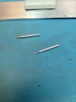
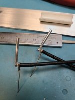
The gamma is 3/32 aluminum tube ( K&S precision metals #8101 ) the core is the centre conductor of the RG174. This fits nicely to the inside diameter (ID) of the aluminum tube. I have cut the tube to 20mm and the centre part of the RG174 to 25mm. This gives extra to expose the wire while leaving a little insulation beyond the tube. A few drops of Gorilla glue has fixed it inside the tube and sealed the end that will be exposed. I will be able to cut the gamma shorter but do not think this is going to be required based on the previous antenna that resonated at 1470mhz. An online calculator put this gamma at 15mm in free space.

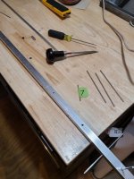
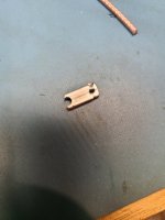
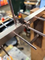
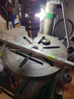
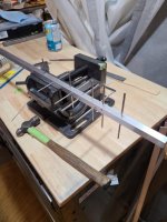
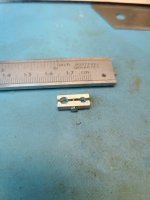
The new design of the bonding clamp started as 1/8 x 1/4 inch aluminum flat stock. I cut this from larger stock I had on hand, but am sure this can be ordered in this size. I then drilled the two holes at 8.5mm on centre for this design. The larger hole is 3.2mm (1/8) and the smaller is 2.4mm (3/32). I then drilled a hole for the stainless steel 2-56 hex head machine screw. This hole size, which I cant remember right now, is for the 2-56 thread tap. I did use the fractional equivalent as I do not have the numbered drill in this size and it worked fine. Once these holes where drilled I cut down the centre with a fine bandsaw to make the halves and then cut them to length. I would recommend keeping the parts attached (not cut to size) to the length of 1/8 x 1/4 flat stock until all the drilling and the centre cut is made. It may not look it in the picture's but these parts are tiny and would be difficult to hold while drilling otherwise. Once the parts have been cut to sized keep them separate as matched pairs, threads can be tapped into one half and the hole in the other half needs to be enlarged a bit so the screw can slip through. I used a high speed dremel like tool for this and a burr. Threads a this size are easy to cut in aluminum and I put the tap in a battery drill on low speed with it sitting on its battery on the bench and hold the piece between my fingers to guide onto the tap. The tap must be dipped into an cutting fluid such as CRC 75500 and thoroughly cleaned of all shavings between each hole. I use a parts cleaner for this. Aluminum is very prone to galling if things are not kept clean and lubricated.

Once the gamma tube and ground wire were soldered to the RG174 I fed it through the boom. Today I will attempt to make the 75 ohm 1/4 wave phasing stubs to get these two polarizations working together. I will wait this time until I know this is going to work before I epoxy the gamma to the boom and seal its connection. ; ) It would be a good idea to test for a short with a multimeter at each step of this process as I have found that this stuff is so small that a stray strand of coax shielding is hard to see with the naked eye.

Thanks,
 

Attachments

  • 01.jpg
    01.jpg
    89.9 KB · Views: 3
  • 02.jpg
    02.jpg
    86 KB · Views: 2
  • 03.jpg
    03.jpg
    51.3 KB · Views: 3
  • 04.jpg
    04.jpg
    66.4 KB · Views: 3
  • 05.jpg
    05.jpg
    57.3 KB · Views: 4
  • 06.jpg
    06.jpg
    50 KB · Views: 5
  • 07.png
    07.png
    357.3 KB · Views: 6

VA3BBY

Member
Joined
Mar 29, 2023
Messages
45
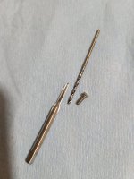
Another day of challenge. I always thought 3 times was the charm and when I got up this morning I thought okay, four. But in this case it is going to be 5. I have included picture 0001 to give a bit of sense of scale to what I mentioned previously, this shows a 2-56 tap, a 1/16" drill bit and a 2-56 machine screw.

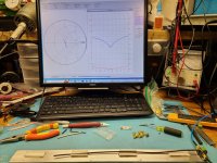
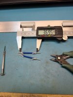
I have spent the day working on the phasing harness and tuning the antenna. The phasing harness was a huge challenge. At this frequency the electrical length of a 1/4 wave coax is so short that I believe you would need a way much better VNA than I could afford to accurately measure this length. I tried 4 times to make this harness and ended up just making it to the Velocity factor specified. I could not shave the coax fine enough to tune. I would get close, then the next cut went very bad. I even spent quite some time to hone my flush cutter with a diamond lap to make it sharper, even this did not help. I think some of the problem is from my VNA not sampling enough, but I am probably wrong?. Maybe the coax is just so short of cable it cant be measured? Electricity can go around the world in something crazy like 7 times per second... so to me this makes 37mm or just shy of 1-1/2 inches, pretty darn short for something to measure. See pictures 0002, 0003, and 0004. I finally gave up and cut this coax to 36.95mm, its calculated electrical length picture 0005. There is no way I could repeat this otherwise for the array and this little harness took me well more than an hour each to carefully make. Needless to say, half the day trying to sort this out. At this length I can cut this coax to one tenth of a mm but I have no idea if that 1 tenth of a mm is the actual length I need based on whether or not the specified Velocity Factor is accurate. I do know at this length, all pieces of this coax will be identical throughout the array. I have made this mistake before haven't I, but in this case I have no choice that I can see.

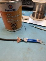
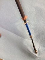
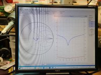
Picture 0006 shows the connection, I used liquid electrical tape for the first 2 tries of the phasing harness then switched to epoxy for third and forth as it was taking to long to dry before I could solder the shielding. Picture 0007 shows the connection of the phasing to the two leads from the gamma match's.

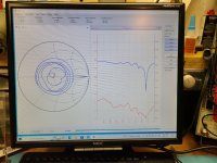
Pictures 0008, 0009, 00010 show tuning the antenna. It does not take many strokes of a file on the end of an element of this size to make a big difference. Between picture 0008 and 0009 was only 5 strokes per element end and picture 00010 shows I went a little to far. I went 20 strokes each. I was trying to shorten the gamma at the same time although I did not originally think I would need to. I also found out there is no proportional correlation between the two so extra caution is needed when trimming both. They was enough gamma tube hanging out I though it may resonate on its own and is why I trimmed. This also had a slight influence on the reflected power but in no way like the huge dip of mag(s11) while trimming the elements, this really showed when I was coming onto frequency. Also, moving the shorting to the point where I didn't think I did had a big effect, I am talking tenths of a mm. I am sure this is reason machine manufactured antennas use a folded dipole driven element, but at these tolerances I do not think human hands could repeat the results so some form of adjustability at the cost of reflected power must be introduced like this gamma match.

My interest is from 1420.405 and up so I am trying to find a happy medium with this antenna designs bandwidth. This is another strange thing, the closer I get to frequency the narrower the bandwidth seems to get. Mathematical calculations of late show the original design as 4.5mm to short. I ended up trimming the antenna today in error by 2.5mm about 1.5mm too much, I think. And to put this into perspective, a human hair is about .12mm

I knew last weekend this was going to take a few more attempts than I had originally thought to come up with a good working model, so last Monday I ordered another batch of boom material. I am sure I have enough element material to make at least another 100 antennas, I just hope I don't need to use that up... At least this time I only made enough elements for this one antenna .

Anyway, I believe now, I have amassed enough information through this R&D and it's no wonder why r&d budgets are so ginormous. I think antenna number 5 will be a good one for me. I also think the term research and development is a code term for a crap ton of mistakes. It should be called CTM.. Although I must say that all the other antennas I have made are good as well but just not at the frequency I have interest...

Maybe later tonight I will set up this antenna #4 in my high tech upstairs lab with the signal generator...

Thanks,
 

Attachments

  • 0001.jpg
    0001.jpg
    68 KB · Views: 3
  • 0002.jpg
    0002.jpg
    165.9 KB · Views: 4
  • 0003.jpg
    0003.jpg
    173.2 KB · Views: 4
  • 0004.jpg
    0004.jpg
    163.2 KB · Views: 4
  • 0005.jpg
    0005.jpg
    77.8 KB · Views: 5
  • 0006.jpg
    0006.jpg
    73.5 KB · Views: 5
  • 0007.jpg
    0007.jpg
    61.8 KB · Views: 4
  • 0008.jpg
    0008.jpg
    149.9 KB · Views: 3
  • 0009.jpg
    0009.jpg
    193.8 KB · Views: 2
  • 00010.jpg
    00010.jpg
    173.8 KB · Views: 3

MUTNAV

Active Member
Premium Subscriber
Joined
Jul 27, 2018
Messages
1,297
Another day of challenge. I always thought 3 times was the charm and when I got up this morning I thought okay, four. But in this case it is going to be 5. I have included picture 0001 to give a bit of sense of scale to what I mentioned previously, this shows a 2-56 tap, a 1/16" drill bit and a 2-56 machine screw.

I have spent the day working on the phasing harness and tuning the antenna. The phasing harness was a huge challenge. At this frequency the electrical length of a 1/4 wave coax is so short that I believe you would need a way much better VNA than I could afford to accurately measure this length. I tried 4 times to make this harness and ended up just making it to the Velocity factor specified. I could not shave the coax fine enough to tune. I would get close, then the next cut went very bad. I even spent quite some time to hone my flush cutter with a diamond lap to make it sharper, even this did not help. I think some of the problem is from my VNA not sampling enough, but I am probably wrong?. Maybe the coax is just so short of cable it cant be measured? Electricity can go around the world in something crazy like 7 times per second... so to me this makes 37mm or just shy of 1-1/2 inches, pretty darn short for something to measure. See pictures 0002, 0003, and 0004. I finally gave up and cut this coax to 36.95mm, its calculated electrical length picture 0005. There is no way I could repeat this otherwise for the array and this little harness took me well more than an hour each to carefully make. Needless to say, half the day trying to sort this out. At this length I can cut this coax to one tenth of a mm but I have no idea if that 1 tenth of a mm is the actual length I need based on whether or not the specified Velocity Factor is accurate. I do know at this length, all pieces of this coax will be identical throughout the array. I have made this mistake before haven't I, but in this case I have no choice that I can see.

Picture 0006 shows the connection, I used liquid electrical tape for the first 2 tries of the phasing harness then switched to epoxy for third and forth as it was taking to long to dry before I could solder the shielding. Picture 0007 shows the connection of the phasing to the two leads from the gamma match's.

Pictures 0008, 0009, 00010 show tuning the antenna. It does not take many strokes of a file on the end of an element of this size to make a big difference. Between picture 0008 and 0009 was only 5 strokes per element end and picture 00010 shows I went a little to far. I went 20 strokes each. I was trying to shorten the gamma at the same time although I did not originally think I would need to. I also found out there is no proportional correlation between the two so extra caution is needed when trimming both. They was enough gamma tube hanging out I though it may resonate on its own and is why I trimmed. This also had a slight influence on the reflected power but in no way like the huge dip of mag(s11) while trimming the elements, this really showed when I was coming onto frequency. Also, moving the shorting to the point where I didn't think I did had a big effect, I am talking tenths of a mm. I am sure this is reason machine manufactured antennas use a folded dipole driven element, but at these tolerances I do not think human hands could repeat the results so some form of adjustability at the cost of reflected power must be introduced like this gamma match.

My interest is from 1420.405 and up so I am trying to find a happy medium with this antenna designs bandwidth. This is another strange thing, the closer I get to frequency the narrower the bandwidth seems to get. Mathematical calculations of late show the original design as 4.5mm to short. I ended up trimming the antenna today in error by 2.5mm about 1.5mm too much, I think. And to put this into perspective, a human hair is about .12mm

I knew last weekend this was going to take a few more attempts than I had originally thought to come up with a good working model, so last Monday I ordered another batch of boom material. I am sure I have enough element material to make at least another 100 antennas, I just hope I don't need to use that up... At least this time I only made enough elements for this one antenna .

Anyway, I believe now, I have amassed enough information through this R&D and it's no wonder why r&d budgets are so ginormous. I think antenna number 5 will be a good one for me. I also think the term research and development is a code term for a crap ton of mistakes. It should be called CTM.. Although I must say that all the other antennas I have made are good as well but just not at the frequency I have interest...

Maybe later tonight I will set up this antenna #4 in my high tech upstairs lab with the signal generator...

Thanks,
Tenths of millimeters is like a quarter of a turn on an N (or even SMA) connector. maybe a micro adjustable phasing arrangement may be in order, as in (I've never seen anyone do this) using the N connector barrel and bullet arrangement but with locking nuts to keep if from changing position once it is set the way you like it....

Also..... Whats going to happen to your antenna when it rains (or frankly even in much higher or lower humidty, than what you have right now)?? An adustable phaser may be what you need.??

I really like my barrel and bullet idea.

In navaids, there was a saying that we would measure with a micrometer, and cut with a hatchet (ie physical implementation is a lot rougher than the math and measurements), you may be rediscovering it.

at 1400 Mhz even a vector voltmeter (the kind I showed in the pictures in an earlier post) wouldn't work well, since it only goes to 1 Ghz :(

Thanks
Joel
 
Status
Not open for further replies.
Top