12 Yagi array

Status
Not open for further replies.

VA3BBY

Member
Joined
Mar 29, 2023
Messages
45
Reaction score
10
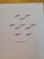
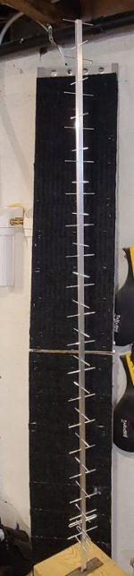
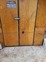
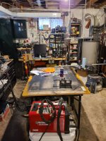
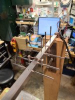
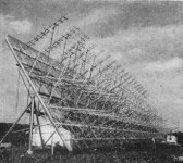
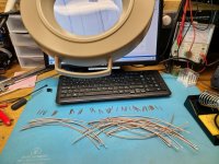
Attached is a picture of the 12 antenna yagi array design I am working on and left it full size so hopefully the info can be zoomed in on. I have picked up the boom material today and now have everything I need to build. The booms are 5 foot 3 inches each and will be end supported by the array frame.

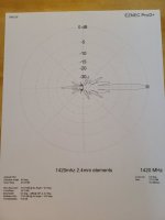
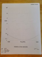
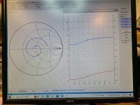
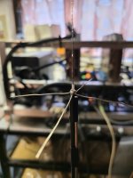
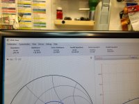
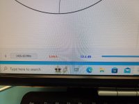
I had to sacrifice the near 1:1 swr on my first design from my first post. I thought I had a supply of 1/16" S.S. rod. The new design is all 3/32" with exception of the Driven and Reflector. Actually its not a Driven element because I am receive only, so what do you call that a Receiven? Anyway, I spent 5hrs of spacing and element length changes, as well, had to change the driven and reflector to eventually 1/4" diameter to arrive at the results you see. The results are the 12 antennas stacked at 450mm apart, I played with the rule of thumb stacking distance as well as from 200mm to 700mm., 200mm is loosely one wavelength ; ) things seemed happy at 450.

It amazes me how much a half a millimeter and rod diameter changes things at this frequency, a piece of coat hanger stuffed into a pl259 worked when I first started 2m... As it is, this is as close as I can get with the materials I have on hand to build the antennas with. I am not sure sure how much SWR effects the receive capabilities of an antenna but if someone has advice it would be greatly appreciated. I don't think it is legal to transmit where I am looking anyway, nor do I have the capability... and half a millimeter is pretty darn and small and so is the rod these antennas want.

To look at the off shore antennas on line and see the 3/8" or so elements they are using for GHZ frequencies and now wonder how that is even possible.

The theoretical gain of this array at 27db is doing pretty good considering the theoretical gain of an 8 foot dish at the same frequency is the same... only this array is only 4 feet wide by 3 feet tall total and a whole lot less wind resistance. Sure says something for the good old technology of a simple yagi antenna...,. maybe I should make it out of coat hangers...

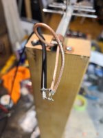
Phasing is my next hurdle. I have lmr-195 and SMA connectors on the way to go from the driven element at equal lengths to a weather proof box just below the array so approximately 6 feet of cable each with a SMA male on the end. Each antenna will be matched with a 4:1 coax balun at the Driven element.

I will probably pick up a 8" or 10" weather proof Grey PVC junction box next time I am at Home Depot to make all the phasing connections. This where things get tricky and I could use some advice with,


Have 12 SMA female bulkhead connectors coming, I have twelve 35db gain LNA's coming to connect directly to the bulk head connectors inside this PVC Box, then its all voodoo.

I have scrounged many plans from the internet, each a bit different, on how to phase these antennas together with coax. I will be using RG174 for this just because there is a mess of things going on inside this PVC box but again if someone has advice on this please chime in. Keep in mind a quarter wave 75ohm phasing stub of coax for this is only 2 inches long at this frequency. I have RG59 coming for the 75ohm requirement. I spared no expense on the coax its all top quality. Times Microwave for most of it.

From this box I have LMR-240 going to the receiver, that will be approximately 25 feet.

Look forward to some friendly advice and maybe some pictures of the antennas you have built with success.

Thanks,
Bob
 

Attachments

  • 20230401_183219.jpg
    20230401_183219.jpg
    127.6 KB · Views: 81
Last edited:

VA3BBY

Member
Joined
Mar 29, 2023
Messages
45
Reaction score
10
Try again with the picture
 

Attachments

  • 20230401_205148.jpg
    20230401_205148.jpg
    102 KB · Views: 76

MUTNAV

Active Member
Premium Subscriber
Joined
Jul 27, 2018
Messages
1,575
Reaction score
1,677
Do you have a way of measuring the phasing on the cables to make all of the cuts correctly. Even at 300 Mhz partially unscrewing an N connector changes the phasing noticeably on phase sensitive applications.

Thanks
Joel
 

merlin

Active Member
Joined
Jul 3, 2003
Messages
3,943
Reaction score
1,889
Location
DN32su
With rule of thumb, measurements can be acceptable. The critical part is the phasing.
There is very little tolerance with Phasing harnesses.
 

VA3BBY

Member
Joined
Mar 29, 2023
Messages
45
Reaction score
10
So far everyone commenting on my venture into the unknown is quick to point out pitfalls, but never seem to offer any know how or what can be used to avoid it.

I am pretty sure I have the equipment I can make work to test harnesses to match the first off (template) as they are made. Not there yet, but from what I have read elsewhere, it could be as simple as clamping a capacitance meter to the length of coax. Or as complicated as trying to figured how I could use my Leader LMV 181 or 200mhz Fluke Scope.... Makes me remember way back when I had to make an RF probe out of copper pipe and a little bit of circuitry for my multimeter. All I think I need is a base figure (reading) to go by for each piece of coax.

I have also learned elsewhere that cutting a phase loop at higher frequencies usually has them end up 5% or so electrically long or lower frequency than desired depending on manufacturer. I think a phone call to Times Microwave could help me sort that out, from what I gather only companies that use lower frequencies to verify their cable velocity are affected this way, maybe the RG series of cable? But I don't pretend to know.

As for backing out the N connecter, you are aware the contact portion of the male pin is only 2mm long. Doesn't have to be backed out far at all before no contact... and if improper tools are used instead of the correct size coax stripper and ratcheting crimping tool, not to mention trying to use too much solder during assembly this pin may not be seated correctly to begin with which will make the matter worse. SMA connectors are even that much less and harder to work with.

If someone has some ideas on at test probe for what I have or the best way to apply what I have to verify cable length that would be great.

thanks,
 

MUTNAV

Active Member
Premium Subscriber
Joined
Jul 27, 2018
Messages
1,575
Reaction score
1,677
So far everyone commenting on my venture into the unknown is quick to point out pitfalls, but never seem to offer any know how or what can be used to avoid it.

I am pretty sure I have the equipment I can make work to test harnesses to match the first off (template) as they are made. Not there yet, but from what I have read elsewhere, it could be as simple as clamping a capacitance meter to the length of coax. Or as complicated as trying to figured how I could use my Leader LMV 181 or 200mhz Fluke Scope.... Makes me remember way back when I had to make an RF probe out of copper pipe and a little bit of circuitry for my multimeter. All I think I need is a base figure (reading) to go by for each piece of coax.

I have also learned elsewhere that cutting a phase loop at higher frequencies usually has them end up 5% or so electrically long or lower frequency than desired depending on manufacturer. I think a phone call to Times Microwave could help me sort that out, from what I gather only companies that use lower frequencies to verify their cable velocity are affected this way, maybe the RG series of cable? But I don't pretend to know.

As for backing out the N connecter, you are aware the contact portion of the male pin is only 2mm long. Doesn't have to be backed out far at all before no contact... and if improper tools are used instead of the correct size coax stripper and ratcheting crimping tool, not to mention trying to use too much solder during assembly this pin may not be seated correctly to begin with which will make the matter worse. SMA connectors are even that much less and harder to work with.

If someone has some ideas on at test probe for what I have or the best way to apply what I have to verify cable length that would be great.

thanks,
You never mentioned exactly what frequency you plan on using.... The higher the frequency the more sensitive to cable lengths.

Besides that, as for practical / hopefully helpful advice...

1. I would recommend avoiding the use of crimp connectors, if you plan on cutting cables to length, they probably have to be cut several times per connector (believe it or not, you can re-use N connectors that aren't crimp type, (even though the rubber washer will be split).

2. I would recommend the use of a vector voltmeter rather than a VNA, I guess it depends on how accurately you want measurements to be.
3. At the frequencies that I'm used to, backing out a connector does make a difference, as does the stability of the cable for temperature and bends (not bends so much, but I haven't checked a lot of cables).


iu


I looked and a vector voltmeter accessory kit is on e-bay for about $200.

The ARRL antenna book used to have a schematic for a simple vector voltmeter.

As for the accessory kit, there is a possibility (just an idea) that you could use the thru line bodies of two bird watt-meters and two plugs that have a BNC connector ( a sniffer ), and make your own. Which would be a good idea, an actual vector voltmeter and its accessory kit are terribly fragile. This would also be useful if you plan on using your o'scope.

Thru line body

iu

A sniffer
iu


All of this stuff is pretty pricey, you may be able to make some of the things you want yourself.

4. If you're looking for a really clean pattern with your array, usually the outer elements are fed (or attenuated), which has the effect of cleaning up the pattern a lot.

Even at HF, a Wullenweber array uses variable phasers to adjust for changes in feed-line characteristics, and that is at HF. The manuals are online and may be a worthwhile read.

Paragraph 5-9 talks about the phasers.


The most important thing is to HAVE FUN, it's a technical adventure :)

Thanks
Joel

I was just able to see your image, you are looking at 1450 Mhz roughly, right....

At those frequencies, you could use a N type barrel and bullet as an adjustable phaser :)

Thanks
Joel
 
Last edited:

VA3BBY

Member
Joined
Mar 29, 2023
Messages
45
Reaction score
10
Hi Joel, thank you very much for the information. Yes, it is 23cm. Although I do have a VNA coming which I was going to use for SWR for the frist section of lines coming from each antenna. What I was taking about above was an older Leader RF Milliamp meter, its has a bottom range is 0 to 1 millivolt, which may be too sensitive. I cant remember why I bought it, maybe when I recapped my IC-R71E's many years ago to follow the alignment instructions. Would this work in some way as opposed to the vector voltmeter you described? I did have the current ARRL antenna book, well when it was current back in around 1998 and I looked for it last weekend but I have moved many time since ,I remember it was blue.

I can understand the backing out of connectors now if I was using them throughout the phasing, what I was planning on doing is coming from each antenna with 2 cables each having a 4:1 balun to dipole. Treating each antenna as a separate horizontal and vertical polarized. From what I read and understand, a bonded to boom folded dipole is around 200 ohms.

From the 4:1 I will make each cable as short as practical with an odd wave but still have slack for a drip loop, probably about 7 wave lengths each cable. These cables will be terminated with SMA male connectors to join with the bottom mounted chassis connectors of my weather proof box.

Inside this weather proof box, the balance of the phasing cables will be soldered direct and include the LNA's. The first phasing from the chassis mount connectors will be 2 dipoles of the same polarization to 1 coax to a LNA . I think I will be using 10 LNA's at this point, I have 16. Then from there to 4 way phase harnesses and maybe a 2way . And finally out to 2 chassis mount female Type N, one for each polarization.

I want to use two runs of coax to the receiver as it has 2 inputs this way I can use the receiver to switch between horizontal and vertical. If I want to go to left or right circular polarization, I will use the phase junction box described in the other post.

There are no plans available anywhere that I can find besides 2-way and 4-way harnesses and I am not educated enough in this field to design my own. I am going to be left with an odd leg of a harness un-used somewhere, can a 50 ohm resistor be put in to make the system think it is an antenna? I can remember making a dummy load with many 50 ohm resistors, so I am thinking this should work. Remember this is receive only array.

I do not understand what you mean by "usually the outer elements are fed (or attenuated)" ?

Yes, I am having fun and in no rush although all the materials I need including the Times Microwave is now here, and this morning the centre of the milky way was due south of me just above the horizon. A spectacular picture on Star Chart and the best wide open view of the sky I have...

Thanks again,
Bob
 

MUTNAV

Active Member
Premium Subscriber
Joined
Jul 27, 2018
Messages
1,575
Reaction score
1,677
Hi Joel, thank you very much for the information. Yes, it is 23cm. Although I do have a VNA coming which I was going to use for SWR for the frist section of lines coming from each antenna. What I was taking about above was an older Leader RF Milliamp meter, its has a bottom range is 0 to 1 millivolt, which may be too sensitive. I cant remember why I bought it, maybe when I recapped my IC-R71E's many years ago to follow the alignment instructions. Would this work in some way as opposed to the vector voltmeter you described? I did have the current ARRL antenna book, well when it was current back in around 1998 and I looked for it last weekend but I have moved many time since ,I remember it was blue.

I can understand the backing out of connectors now if I was using them throughout the phasing, what I was planning on doing is coming from each antenna with 2 cables each having a 4:1 balun to dipole. Treating each antenna as a separate horizontal and vertical polarized. From what I read and understand, a bonded to boom folded dipole is around 200 ohms.

From the 4:1 I will make each cable as short as practical with an odd wave but still have slack for a drip loop, probably about 7 wave lengths each cable. These cables will be terminated with SMA male connectors to join with the bottom mounted chassis connectors of my weather proof box.

Inside this weather proof box, the balance of the phasing cables will be soldered direct and include the LNA's. The first phasing from the chassis mount connectors will be 2 dipoles of the same polarization to 1 coax to a LNA . I think I will be using 10 LNA's at this point, I have 16. Then from there to 4 way phase harnesses and maybe a 2way . And finally out to 2 chassis mount female Type N, one for each polarization.

I want to use two runs of coax to the receiver as it has 2 inputs this way I can use the receiver to switch between horizontal and vertical. If I want to go to left or right circular polarization, I will use the phase junction box described in the other post.

There are no plans available anywhere that I can find besides 2-way and 4-way harnesses and I am not educated enough in this field to design my own. I am going to be left with an odd leg of a harness un-used somewhere, can a 50 ohm resistor be put in to make the system think it is an antenna? I can remember making a dummy load with many 50 ohm resistors, so I am thinking this should work. Remember this is receive only array.

I do not understand what you mean by "usually the outer elements are fed (or attenuated)" ?

Yes, I am having fun and in no rush although all the materials I need including the Times Microwave is now here, and this morning the centre of the milky way was due south of me just above the horizon. A spectacular picture on Star Chart and the best wide open view of the sky I have...

Thanks again,
Bob
I think you are talking about a 50 ohm termination, just terminate one of the inputs to the combiner.... or you could use


or maybe even make your own, I know for MW its (apparently easily) doable, not sure about 1500MHz

In a phased system that is looking for a clean pattern, generally the outer elements are attenuated a little which cleans up the pattern, see paragraph 5-12 of the wullenweber pdf I linked to , although the wullenweber also does time delay things, still the outer elements are attenuated more as they get towards the edge of the array.

Having a bunch of LNAs may be difficult to match amplitude wise


You could probably use the line sampler in this book (construction wise, not as a directional coupler. Two of them fed

signal source --> BNC-->sampler1-->BNC--> cable under test-->BNC--> second coupler -->BNC--> dummy load
] ]
] ]
Vector voltmeter input 1 input 2


or the far better


I think the vector voltmeter schematic was in the blue handbook that you had.

Thanks

Joel


There is a remote possibility that I've discounted the value of a VNA


Thanks
Joel
 

VA3BBY

Member
Joined
Mar 29, 2023
Messages
45
Reaction score
10
Good morning,

That 12 way power splitter would be ideal but the price and I would need 2 of them.. I don't want to go to work now, would much rather spend it reading. I will take one more look for my blue book to review the VV, it may be in the attic of my shop. This is just the information I need Joel and was lacking. I can build things to demanding and exacting standards as long as I have the plans to go by and someone to point me in the right direction.

Thank you again Joel, I will let you know how I make out.
Bob
 

MUTNAV

Active Member
Premium Subscriber
Joined
Jul 27, 2018
Messages
1,575
Reaction score
1,677
Good morning,

That 12 way power splitter would be ideal but the price and I would need 2 of them.. I don't want to go to work now, would much rather spend it reading. I will take one more look for my blue book to review the VV, it may be in the attic of my shop. This is just the information I need Joel and was lacking. I can build things to demanding and exacting standards as long as I have the plans to go by and someone to point me in the right direction.

Thank you again Joel, I will let you know how I make out.
Bob
Great, the manual for the Wullenweber FLR-9 array has a whole lot of really cool information about it regarding antennas.

Maybe you could just find how to make 2 element combiners and use a lot of them?


Thanks
Joel
 

VA3BBY

Member
Joined
Mar 29, 2023
Messages
45
Reaction score
10
I think you are right, it reminds me of a water treatment plant I used to operate. The UV bank was fed in the same way so each of the units had the exact same water volume introduced to them, what do you call that, cascading, I cant remember? I see this pattern as well on PCB power divider schematics. There is a 2 into 1 PCB power divider available from those other guys for $1.32 each, but I would need to figure out shielding cans for them, then it gets complicated for space. So I think I am going to stick with tried and true Coaxial phasing. Besides, you really can't say "I made that" with off the self stuff or online antenna calculators.

I received my new VNA today so looking forward to learning how to use it. There is a video on youtube on how to use this to match phasing cables.

I spent some time today to draw up a polygon array in autocad for the xyz coordinates and then plopped them into EZNEC with the 20 element antenna I have settled on for ease of build and material use. The results were a very pleasant surprise. I have not seen an array like this on the internet, and I had thought for probably a good reason. But not so, my findings show it does a little bit better, not much. 27.08 dBi for a right angled array and this 27.24 dBi for the polygon. I did it because it is more the shape of a satellite dish and just thought it seemed a reasonable approach to get a circular beam.

Maybe this gives a new meaning to thinking outside a box.... LoL

The side lobe pattern on the polygon is much tighter and it has a narrower beamwidth at 5.4 degrees although the sidelobes have a different shape than usual. You will see, I will anticipate the negative comments.

I started to build the frame for the array because it was such a nice day out. It worked out to be a little more than 6 feet cross from the model. I tried many different spacings with the modeling and this is where it seemed happy. It is going to be 6 antennas around the perimeter then steps down to 3 then 1 in the centre. 10 antannas total with 20 elements each for 27.dBi gain total.

The first antenna I modeled a few weeks ago and built was 22 elements. It had optimized spacing for gain based on a internet calculator. I put this antenna into a 12 antenna array model for a total of 28.33 dBi gain and a 5.8 degree beamwidth. Again, I spent very much time with varying stacking spaces.

So maybe there is something to say about experimenting with polygons? I chose a hexagon because I only had enough material left to make 11 antennas. I bet you could do even better with an Octagon....

Anyway, like you said Joel, as long as I am having fun, And that it is..

Thanks,
Bob
 

Attachments

  • a.jpg
    a.jpg
    37 KB · Views: 15
  • b.jpg
    b.jpg
    48.9 KB · Views: 13
  • c.jpg
    c.jpg
    25.8 KB · Views: 15
  • d.jpg
    d.jpg
    27.8 KB · Views: 18
  • e.jpg
    e.jpg
    108.4 KB · Views: 17

MUTNAV

Active Member
Premium Subscriber
Joined
Jul 27, 2018
Messages
1,575
Reaction score
1,677
I think you are right, it reminds me of a water treatment plant I used to operate. The UV bank was fed in the same way so each of the units had the exact same water volume introduced to them, what do you call that, cascading, I cant remember? I see this pattern as well on PCB power divider schematics. There is a 2 into 1 PCB power divider available from those other guys for $1.32 each, but I would need to figure out shielding cans for them, then it gets complicated for space. So I think I am going to stick with tried and true Coaxial phasing. Besides, you really can't say "I made that" with off the self stuff or online antenna calculators.

I received my new VNA today so looking forward to learning how to use it. There is a video on youtube on how to use this to match phasing cables.

I spent some time today to draw up a polygon array in autocad for the xyz coordinates and then plopped them into EZNEC with the 20 element antenna I have settled on for ease of build and material use. The results were a very pleasant surprise. I have not seen an array like this on the internet, and I had thought for probably a good reason. But not so, my findings show it does a little bit better, not much. 27.08 dBi for a right angled array and this 27.24 dBi for the polygon. I did it because it is more the shape of a satellite dish and just thought it seemed a reasonable approach to get a circular beam.

Maybe this gives a new meaning to thinking outside a box.... LoL

The side lobe pattern on the polygon is much tighter and it has a narrower beamwidth at 5.4 degrees although the sidelobes have a different shape than usual. You will see, I will anticipate the negative comments.

I started to build the frame for the array because it was such a nice day out. It worked out to be a little more than 6 feet cross from the model. I tried many different spacings with the modeling and this is where it seemed happy. It is going to be 6 antennas around the perimeter then steps down to 3 then 1 in the centre. 10 antannas total with 20 elements each for 27.dBi gain total.

The first antenna I modeled a few weeks ago and built was 22 elements. It had optimized spacing for gain based on a internet calculator. I put this antenna into a 12 antenna array model for a total of 28.33 dBi gain and a 5.8 degree beamwidth. Again, I spent very much time with varying stacking spaces.

So maybe there is something to say about experimenting with polygons? I chose a hexagon because I only had enough material left to make 11 antennas. I bet you could do even better with an Octagon....

Anyway, like you said Joel, as long as I am having fun, And that it is..

Thanks,
Bob

Your in good company with an octagonal array :) Well, kind of, at least it looks like it on the surface..

Thanks
Joel

iu


This gives a slightly better idea of what I mean by slightly attenuating the outer elements of an array.
 
Last edited:

VA3BBY

Member
Joined
Mar 29, 2023
Messages
45
Reaction score
10
Thank you Joel for the link, Yeah, thought I was onto something spectacular with a hexagon array. Attached is another variant, but I do like the gain and still have not seen a Yagi Hex. I was looking at horn antenna designs recently, as well as a calculator and for the same gain as this 10 Yagi antenna array the horn would need to be a little better than six metres long. That's pretty fricken big even for us up north Canadians... I maintain, there is something to be said for the capabilities of combined Yagi's. Besides, it looks cool when they are stacked.

So I have done some work, cut my 400 plus elements some time ago and put together an antenna for test with my new VNA. Well, the VNA was defunct, it wouldn't even measure a 1 wavelength piece of coax at this frequency and after a few minutes of operation at this frequency it became very unstable and worse the longer it was turned on to a point where it stopped working altogether . It is on its way back to where I got it after more than a week of nonsense from seller. Plus, I have realized through study that all of my elements are 2mm to short. The calculator I used gave a value for boom correction of 6875. I took this as a mm dimension and made all my elements 7mm longer than EZNEC dims just because I can not cut to a .0125 mm accuracy . Well this dimension is actually is .6875 percent of the boom dimension... live and learn. LoL, only 400 or so mistakes. They are all accurately cut mistakes though....

Have sent along a couple pictures, Have made the new elements today. Have also made length jigs to centre the new elements on the boom. These need to be less than .5mm tolerance so figured this is best practice, my eyes are not that good anymore for judgement. And Joel, I am begining to understand your much earlier comment of temperature error at this frequency, I think your comment was largely to do with coax, but... . Just through the cutting process of the element centering jigs, I had to re-zero my Vernier several times as it would vary up to .2mm from ambient and most likely my hand heat over the course of a couple hours of cutting. That's not far from a 1/2 mm tolerance required.

I have abandoned the use of a folded dipole driven element and 4:1 coax baluns as they are just too unwieldly at this frequency, everything is so tiny. I am investigating both T and Gamma match at this point and have started dialog with someone from afar. But if anyone has some ideas, please. I know receive only antennas are different but do not understand what will work or what is acceptable in practice..

I was originally going to just staked (peen, punch) the boom to elements to make the electrical bond. But after my several weeks experience of how critical dimensions are, I thought it would not be too long before atmosphere corrosion messed this up. I have brought my sons TIG welder to my basement shop to make the element to boom connection permanent. Although I am not looking forward to that many tiny welds..

I thought I would experiment with a solid wire gamma, although it would work by varying the distance of the gamma rod to boom by tilting back and forth for capacitance to get a 1:1 VSWR. It was so seriously sensitive that I did not think I could repeat it 10x accurately. Also, it was extremely narrow banded, I mean if you had one frequency you wanted to work, this would be ideal. I have ordered in some tiny aluminum tube and thicker than usual insulation on wire to fit the ID of this tube. This should make a proper Gamma or T match. I would prefer T as it seems more balanced to me. To do this, I have increase the size of the reflector and driven from 3/32 or 2.4mm to 1/8 or 3.17mm.

I still need to remove the elements from the antenna hanging from the ceiling and install the new elements I cut today , the replacement VNA should be here sometime this week. Still need to sort out a jig/stand for TIG welding and then more fun begins.
 

Attachments

  • hexagon array.jpg
    hexagon array.jpg
    55.3 KB · Views: 8
  • 20230417_132848.jpg
    20230417_132848.jpg
    97.2 KB · Views: 6
  • 20230430_173521.jpg
    20230430_173521.jpg
    81.2 KB · Views: 8
  • 20230430_173731.jpg
    20230430_173731.jpg
    131.1 KB · Views: 11
Last edited:

VA3BBY

Member
Joined
Mar 29, 2023
Messages
45
Reaction score
10
I came across an article from 1956 that had me rethink maintaining the options of horizontal, vertical and circular. I had done a lot of research on what was the best way to polarize an array for radio astronomy but did not find much on the subject and is why I initially wanted to leave my options open. This attached photograph has made me decide to phase the vertical and horizontal together at the antenna and have done this with really good quality RG179. I think I will also orient the antennas in a X manner, maybe this will offer some extra noise rejection? Although here, the noise my random wire dipole at 1420.405 receives is a constant -135 dBm no squelch or filters. I don't think that is too bad but maybe I am wrong.

I am still amazed at how little information is available for this kind of antenna venture. I also wonder how critical the phasing really is for this kind of receiving. Just look at the photo from 1956, talk about a cable nightmare not to mention without the equipment we have today. Also just look at the kilometres array in Australia with the hundreds and hundreds of dipoles spread out on chicken wire with cable running every which way all over the desert as far as the eye can see.... LoL

Anyway, I think the other changes I have made were very positive, going from 2.4mm reflector and driven to 3.17mm and going from .100 aluminum sheet for the shorting bar to .125 bar. I went back to a solid rod and to a t-match from gamma with help from a new friends calculator in the Ukraine. See attached pictures and result. Right now I am making the full set of T-match's 2mm longer as this shifts the capacitance with frequency.

I am also going to see how trimming the 7/4 wavelength RG179 (75ohm) matching stubs affects the frequency centre. The green dot in the reflected power sweep is the frequency I designed the antenna for and was hoping to have the lowest VSWR although right now it is sitting at 51.8 ohms but is showing a 1.7 swr. I am also going to see what happens if I trim the longer piece of 179 to match the forward 1/4 wave offset driven. This is just a testing prototype for experimenting and I am curious, because what you read doesn't always seem to be the case.
This T-match reminds of the orange drop capacitors I was searching for when rebuilding an old guitar amp and if I can find a jar of bright orange Testors, I may just paint them for fun. Adjusting the distance between rod and boom does varies the capacitance. I am using epoxy to encapsulate the solder joints, matching rods and end of coax. This has allowed me to file a consistent flat to have a 3mm air gap from boom which seems to be the happy spot for this antenna. I will then epoxy this where it meets the boom once the shorting bars are crimped in place.

Oh ya, I also whipped together a 1/4 wave just to verify the VNA operation at this frequency.
 

Attachments

  • 20230506_130237.jpg
    20230506_130237.jpg
    82.5 KB · Views: 10
  • 20230506_130429.jpg
    20230506_130429.jpg
    170.8 KB · Views: 10
  • 20230506_130259.jpg
    20230506_130259.jpg
    52.5 KB · Views: 9
  • radio-waves-jupiter-venus-pe-september-1956-3_small.jpg
    radio-waves-jupiter-venus-pe-september-1956-3_small.jpg
    30.6 KB · Views: 12
  • 20230506_130859.jpg
    20230506_130859.jpg
    56.6 KB · Views: 9

MUTNAV

Active Member
Premium Subscriber
Joined
Jul 27, 2018
Messages
1,575
Reaction score
1,677
Great... If I can put forward another idea about the 90 degree stub.... consider also being able to throw a barrel and a bullet in line so you can see how much it changes. Also... What kind of accuracy are you getting with the VNA? to the tenths of degrees or degrees. and maybe see how much the phasing changes just by partially unscrewing an N connector.

Thanks
Joel
 

G7RUX

Active Member
Joined
Jul 14, 2021
Messages
709
Reaction score
434
I am not sure sure how much SWR effects the receive capabilities of an antenna but if someone has advice it would be greatly appreciated.”

In general, antennas are reciprocal devices so mismatch will affect the receive and transmit performance in the same way, introducing losses, etc. However, in a receive system you won’t have the possibility of causing overheating with large mismatches so you just need to consider the extra losses.
 

VA3BBY

Member
Joined
Mar 29, 2023
Messages
45
Reaction score
10
Wanted to reply to your comments Joel because my findings of your last question is humorous, besides my solder iron needed to cool down and my hands need a break. The first attached picture maybe answers your degrees question? All these numbers are really just Japanese to me, I look at the ohms and the reflected power the rest is just nonsense .

The first VNA I got in was a saa-2n, it was supposed to be good to 3Ghz but was very unstable after just a few minutes at 1.4Ghz then it would just not communicate, it had N connectors on it. I learned later it relies on harmonics after 900Mhz. This replacement VNA is supposed to be good to 4.4Ghz and does not use harmonics, it has been running all day on the antenna while I am cutting and soldering components and is just varying small decimal points back and forth, probably me moving around near antenna, it has SMA. It cost twice as much but still very inexpensive compared to commercial units. It is the original developer V2 Plus4.

The funny part. I remember questioning you about backing out an N connector quite some time ago in my uninformed arrogance. Well, I am using SMA connectors now and there is even less movement required before they disconnect completely, maybe 1.5mm? The second picture attached is with the SMA snug and the third is with the nut a few turns loose.

As you can see by the results (the red number is VSWR). I must offer you my most humble apology for my flippant reply to your original comment about backing out connectors, and hope you will accept this. Also, that I must run around to all my connectors and back them off a few turns, because apparently I get a better SWR with things loose the way I have my stuff set up...

I have over the course of my learning curve, discovered how much a fraction of mm makes a difference up in these frequencies. I have also learned through my experience several ways, actually a lot of ways, on how not to build or match a Yagi...

I do not know what a barrel and a bullet is. I did calibrate the VNA with its stub coax and the adapter I needed to connect to my antenna during the process though.

And thank you G7RUX, your comment is appreciated, and I am starting to understand this while building this array as if it was going to transmit. Just always hopeful of an easier way with less headaches...

Thanks,
Bob
 

Attachments

  • 20230506_155232.jpg
    20230506_155232.jpg
    143.8 KB · Views: 3
  • 1.jpg
    1.jpg
    190.8 KB · Views: 2
  • 2.jpg
    2.jpg
    182.3 KB · Views: 2

MUTNAV

Active Member
Premium Subscriber
Joined
Jul 27, 2018
Messages
1,575
Reaction score
1,677
No problem with the backing out thing...Just use your calibrated fingers to make sure everything has the same tension on it.

They barrel/bullet combo just extends a line a little (but relatively fixed) bit, since they are pretty secure, they make a good check when looking at two sides of a device under test to verify if something is a few degrees advanced or retarded (so you don't cut the wrong side). You just switch from one test side to another to check.

I didn't see anything in your pictures that indicate phasing, I don't currently use a VNA though, maybe someone with more experience can help.

I'm glad your learning a lot, I've read that at the higher frequencies its more machining skill than conventional electronics :)

honestly, if it weren't for the lessons to be learned from doing this, then I would have more strongly recommended using a dish for just the end result.

If you have access to ARRL files, Aug 1972 version of QST shows what I'm talking about, and the big "problem" would have just been the feed. Basically a 12 foot dish made from aluminum poles and fishing line, and aluminum screen material, that could be folded down to 6 feet for easy movement by car.

Thanks
Joel


61NC8dNgdvL._AC_SL1500_.jpg


4 bullets

81IlbtgHwHL._AC_SL1500_.jpg


A barrel...
 

VA3BBY

Member
Joined
Mar 29, 2023
Messages
45
Reaction score
10
LoL, although they are very experienced, I don't think they are calibrated for this particular application...

I finished soldering the T-matches and have applied the first side of the, um, black drops. I really am going to paint them orange.
I used the epoxy mostly because of my concern of the centre conductor fatiguing. See attached pictures of process. This stuff is so small I even used the magnifier to verify no stray strands would cause a short. I wonder how they can make wire so thin it is hard to see?

So a very interesting factoid, as I mentioned earlier, I trimmed the phasing stubs 9mm. Basically cut off the soldering shown in the previous picture hanging out the back of the antenna boom. . I did this because that is what I have my coax stripper set at and thought I would just cut back to un altered coax and start over. That 9mm shifted the centre frequency 44Mhz. More than 20 more than I would have been happy with. Crazy. See picture and compare with previous, just wow. What's a 1/4 inch, a little more than 6mm...

But this makes sense from what I have read about coax velocity factor, it all depends on what frequency the manufacturer tests the cable at. I have read that this variable can cause your coax to be up to 5% electrically long. In my case it was not 5% but the stubs were long as my centre frequency was lower than I was hoping for. I used the specified 66% VF or this cable. I am still going to cut a 1/4 wave off of the longer cable just to see what happens and will advise. I am expecting this to not go so well but am curious.

Although VNA's are supposed to be capable of measuring coax by time domain , I do not think they are capable of measuring the resonate frequency of a piece of coax, which I think is needed here. But I am probably wrong.... and besides, how do you connect a piece of cut coax to the instrument for test before fittings are added is a question I would like to be enlightened on?

I would like to see that article you mentioned but don't have access to it. From the coax I have saved by phasing at antennas, I have a thought of turning my West facing roof into a dipole array, it is sloped at 45 degrees and would not be opposed to adding a layer of chicken wire to it.. But this is a project for next year..

Thanks
 

Attachments

  • 20230506_175443.jpg
    20230506_175443.jpg
    164.5 KB · Views: 5
  • 20230506_184144.jpg
    20230506_184144.jpg
    171.8 KB · Views: 7
  • 20230506_191243.jpg
    20230506_191243.jpg
    129.7 KB · Views: 8
  • 20230506_193335.jpg
    20230506_193335.jpg
    133 KB · Views: 8
  • 20230506_194637.jpg
    20230506_194637.jpg
    208.4 KB · Views: 6
Status
Not open for further replies.
Top