
You are using an out of date browser. It may not display this or other websites correctly.
You should upgrade or use an alternative browser.
You should upgrade or use an alternative browser.
AOR 8600mkII
- Thread starter merlin
- Start date
- Status
- Not open for further replies.
kg4ehv
Radio Active
I really enjoy using mine.
bearcatrp
Member
It is a great receiver but you need a PHD to program that thing. I bought one of the 1st ones in late 90’s. The short time I owned it, it worked well. I sold it and bought a RS Pro 26, which is still working today. Good luck with yours.
Yea, I see a little learning curve but doesn't look as bad as my BCT15X.It is a great receiver but you need a PHD to program that thing. I bought one of the 1st ones in late 90’s. The short time I owned it, it worked well. I sold it and bought a RS Pro 26, which is still working today. Good luck with yours.
Ubbe
Member
AR8200 are using its AGC circuit for AM reception also in FM mode. When you get closer to a transmitter it will reduce its gain and can completely loose the signal you are monitoring.
This will have the effect that you will never encounter overload issues or intermod and will be fooled to think that it has an excellent receiver performance.
It's a good scanner and one problem could be the usual AOR one that you cannot turn each scan bank on and off. They are linked together so if you have bank 1 enabled you could also have bank4-5-6 linked to it that will be scanned. If you then would like to include bank 3 then you have to edit the bank1 link configuration to add that, or make a new link that include bank 1-3-4-5-6 that you then select to scan. There's no quick way to exclude or include a memory bank.
/Ubbe
I will likely be using it for 6 meters and down, sort of compliment my Airspy HF-discovery.
Specs say it is good down to 100 KHz, maybe grab some NDBs. I may stuff the channel banks with some active frequencies, but scanning will probably be more frequency hunting. the bandscope should help with that.
The hard catch for me is CHP, VHF low, maybe this will do OK.
Specs say it is good down to 100 KHz, maybe grab some NDBs. I may stuff the channel banks with some active frequencies, but scanning will probably be more frequency hunting. the bandscope should help with that.
The hard catch for me is CHP, VHF low, maybe this will do OK.
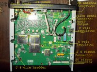
Well, smooze. I found a cratered switch IC on the microcontroller board. Probing a bit with the scope, this is brain dead.
The IC isn't identified on the board, so a brick wall until I can find a parts list and board diagrams.
The IC isn't identified on the board, so a brick wall until I can find a parts list and board diagrams.
Ubbe
Member

That is the boost converter circuit. DVM shows 26 volt and 4.8 volt in.
Ubbe
Member
Is it a logic switch IC that has a crater in it? Then that seems odd.
Download that schematic and check what IC it is. I can't see it in your picture. Is it the one with those brown wires around it, that seems like someone has already tried to fix it by bridging something that stopped working.
/Ubbe
Download that schematic and check what IC it is. I can't see it in your picture. Is it the one with those brown wires around it, that seems like someone has already tried to fix it by bridging something that stopped working.
/Ubbe
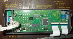
In 'inside 1' across the bottom there are 2 swithches, the one inquestion is south of the flash IC, the other,does have a mod,
and certain it is factory. I am just hoping the service manual I ordered has all the detail I need.
All part of a simple microcontroller and technology is over a decade old.
I'm thinking an overvoltage spike, the supply with it is bad and something got hot.
I do have a downloaded schematic, close but not exactly matching the radio.
This is a second edition radio so newest of the clade. Very clean, looks new.
Ubbe
Member
The schematic that you can download when clicking on my picture are a mkII one.
That 6 pin IC are probably IC5 that are a voltage regulator that can be switched on and off from the CPU and sits directly on the input voltage, before the on/off switch. So will then be a prime suspect. Its a TK11245 with a P45 marking on it and you get a pack of 25 for $7 + $10 shipping from UK at Ebay. Haven't found any supplier in US.
/Ubbe
I'll look into that. The schematic I have is for the mkII, What I really need to do is separate all the devices for the micro board from the RF board.The schematic that you can download when clicking on my picture are a mkII one.
That 6 pin IC are probably IC5 that are a voltage regulator that can be switched on and off from the CPU and sits directly on the input voltage, before the on/off switch. So will then be a prime suspect. Its a TK11245 with a P45 marking on it and you get a pack of 25 for $7 + $10 shipping from UK at Ebay. Haven't found any supplier in US.
/Ubbe
One Odity with my schematic, it shows a 32 pin (J2 (Ribbon)) on the micro board that does not exist,really confusing.
That IC5 you speak of is used for the backlight dimmer (a new option for this radio.) It is switched from the micro which is dead,
As is the backlight power.
I have a manual comming from AOR, I hope the schematic is not as confusing, and a parts list with locations.
Won't get here til New years eve.
Ubbe
Member
Then you have a different schematic than me. IC5 are the regulated power to the memory.That IC5 you speak of is used for the backlight dimmer (a new option for this radio.) It is switched from the micro which is dead,
As is the backlight power.
IC6 and IC7 are the backlight in my schematic and the schematic says it is for mkII. I wouldn't excpect any blown LED driver to make the CPU stop working but a power regulator to the memory chip would. You can probably order a TK11245 right now while waiting for your service manual to arrive. I googled the chip and didn't find any in US but perhaps if you specifically go to Mouser, DigiKey and those usual places they might have it.
/Ubbe

OK, I dug deep into this, you are right, IC5 supplies VDD to the flash, CPU, and the latch, that all measures 4.5 volts power on.
IC 6 and 7 power the backlight and dimmer. Also where 2 jumper mods have been made. I can force this on and works, juust no hi from the CPU.
The hurt time is this is looking like the CPU has failed. I can replace this if I have to and I do have sources for most of these devices.
I can make this work, just a lot more labor than expected.
January maybe.
Ubbe
Member
I wouldn't go for the CPU as the first thing to suspect. Check its reset pin if that works as it should. I have had several cases where the reset circuit had a bad capacitor that forced it to a permanent reset.
Then check the chip enable pin of the 29c512 flash if the CPU tries to read its firmware, that then would indicate that the CPU actually runs but there's a memory problem. Those flash chips can fail or have gone corrupt. Maybe you read the thread about AOR most advanced receiver that seem to self corrupts its program memory and needs to be sent to Japan. AOR haven't hired the best software writers.
/Ubbe
Yes, I checked the reset circuit, it checks OK, but I have to pull the cpu pin high as that pin on the CPU is low.
I have seen that problem myself with other systems.
Im not going to condemn the CPU just yet, I need to verify the clock crystal and caps are working.
The scope shows no clock either. Anyway, a replacement cpu is under $3.00, so ordered one, like better have it and not need it than need it and not have it.
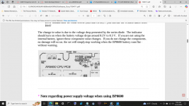
I found a partial clip from the official AOR manual, and it shows the CPU board with parts.
I hace no board images other thanwhat I am shooting.
I have seen that problem myself with other systems.
Im not going to condemn the CPU just yet, I need to verify the clock crystal and caps are working.
The scope shows no clock either. Anyway, a replacement cpu is under $3.00, so ordered one, like better have it and not need it than need it and not have it.
I found a partial clip from the official AOR manual, and it shows the CPU board with parts.
I hace no board images other thanwhat I am shooting.
Attachments
Ubbe
Member
Those CPU's have their own internal 60kb flash memory that needs to have the specific AOR software in it to operate. It can be programmed in circuit from the scanners RS232 port but I haven't seen that AOR boot loader software available anywhere.
/Ubbe
/Ubbe
- Status
- Not open for further replies.
Similar threads
- Replies
- 14
- Views
- 1K
- Replies
- 18
- Views
- 1K
- Replies
- 2
- Views
- 350
- Replies
- 14
- Views
- 2K