BTT SELECT-78 770/850 MHz Public Safety Filter

KevinC

Other
Super Moderator
Joined
Jan 7, 2001
Messages
11,520
Location
Home
I would have to DF the site but its probably one I can see at 263yds from my tower as measured with a laser range finder. I will have to see if there is a company sign on the building. I'm assuming its 5G as the site has been there for 30yrs and the 700MHz stuff just went on the air within the last year or so.

It’s probably not 5G. Is it Band 14?
 
Joined
Jan 4, 2005
Messages
1,738
Location
Soledad, CA
Band 12,13,14 is LTE 4G most of 5G is on 600mhz or C-band 2x/3xGHZ

Band 14 is popping every where because it's first net priority for public safety
 
Last edited:

KevinC

Other
Super Moderator
Joined
Jan 7, 2001
Messages
11,520
Location
Home
Band 12,13,14 is LTE 4G most of 5G is on 600mhz or C-band 2x/3xGHZ

Band 14 is popping every because it's first net priority for public safety

And Band 14 can have ERP’s of 1 kw in some cases. Get in the fresnel zone of a sector like that and your RX ability will go to crap very quickly.
 

amcferrin90

Member
Premium Subscriber
Joined
Mar 11, 2015
Messages
276
Location
Pickerington, OH
I just happened to have an extra one of these Comba FP-78-IN-1 public safety filters left over from a project. Works fantastic. It's a little pricey for your average guy. It blocked out a Sprint B26 site 500 feet away.


@prcguy something to consider for your application.
 
  • Like
Reactions: btt

btt

Banned
Banned
Joined
Mar 11, 2020
Messages
2,585
Location
Wa State
I just happened to have an extra one of these Comba FP-78-IN-1 public safety filters left over from a project. Works fantastic. It's a little pricey for your average guy. It blocked out a Sprint B26 site 500 feet away.


@prcguy something to consider for your application.
Very nice looking $1700 filter, but it does have up to 5 dB of insertion loss in the pass band. Something to consider..
 

btt

Banned
Banned
Joined
Mar 11, 2020
Messages
2,585
Location
Wa State
It occurred to me today that I probably didn't convey the reason for the high losses in a passive filter of this type. The main issue is that we are dealing with two different pass bands in these combined 770/850 systems. A subscriber receiver will switch between separate filters / signal paths depending on the frequency in use. In the case of the SELECT78 filter, we are trying to avoid the need for RF switching. If you refer back to the block diagram, you will see that the filter works by splitting the signal (3dB of loss), filtering the two pass bands, then recombining (3dB). Then you also have the losses for each of the interdigital filters (~ 3 dB). If we only need to filter either the 770 or the 850 band only, then the losses will be low. It would be the loss of a single interdigital filter. (< 3dB total). I was planning on separate passive filter products for the individual bands as well.
 

btt

Banned
Banned
Joined
Mar 11, 2020
Messages
2,585
Location
Wa State
Another thing that I forgot to mention regarding the s-parameter plots in the first post of this thread. The characterization of the filter was done with a swept input power level of -15 dBm. It looks identical with a swept input power of 0 dBm. It is a very high IP3 LNA that is suitable for use with high-order QAM modulations. The only way to achieve higher IP3 specs would be with a balanced amplifier design.

The 4th and final filter assembled was shipped to an RR user and BTT customer who is having issues with LTE. He will be testing with the original P25RX, RTL, AirSpy in fixed and mobile situations.
 

prcguy

Member
Joined
Jun 30, 2006
Messages
15,366
Location
So Cal - Richardson, TX - Tewksbury, MA
I might suggest you have your testers use a spectrum analyzer or at least a spectral display on an SDR to accurately measure carrier to noise ratio and preferably with some filtering or averaging to minimize noise floor excursions. And zero in on some carriers so somethign like a 1dB change in C/N can be detected. A lot of people might see a 3-4dB increase in raw signal level and think everything is great when in reality their C/N has degraded several dB.

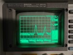
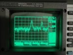
Here is a picture of my filter/preamp getting blitzed with the first picture being a direct connection to the antenna with no preamp or filter. The second picture is with a 700MHz high pass before a preamp. Notice the higher signal levels and noise floor but degraded S/N in the second picture and some frequency ranges have lots of dancing ghost signals or IMD floating through the spectrum with the preamp on. This was with 10dB/div and I would normally use 5dB or less per div to show more detail but this particular analyzer doesn't have adequate features for that.


1674498894955.jpeg

1674498926959.jpeg

Another thing that I forgot to mention regarding the s-parameter plots in the first post of this thread. The characterization of the filter was done with a swept input power level of -15 dBm. It looks identical with a swept input power of 0 dBm. It is a very high IP3 LNA that is suitable for use with high-order QAM modulations. The only way to achieve higher IP3 specs would be with a balanced amplifier design.

The 4th and final filter assembled was shipped to an RR user and BTT customer who is having issues with LTE. He will be testing with the original P25RX, RTL, AirSpy in fixed and mobile situations.
 

btt

Banned
Banned
Joined
Mar 11, 2020
Messages
2,585
Location
Wa State
I might suggest you have your testers use a spectrum analyzer or at least a spectral display on an SDR to accurately measure carrier to noise ratio and preferably with some filtering or averaging to minimize noise floor excursions. And zero in on some carriers so somethign like a 1dB change in C/N can be detected. A lot of people might see a 3-4dB increase in raw signal level and think everything is great when in reality their C/N has degraded several dB.

Here is a picture of my filter/preamp getting blitzed with the first picture being a direct connection to the antenna with no preamp or filter. The second picture is with a 700MHz high pass before a preamp. Notice the higher signal levels and noise floor but degraded S/N in the second picture and some frequency ranges have lots of dancing ghost signals or IMD floating through the spectrum with the preamp on. This was with 10dB/div and I would normally use 5dB or less per div to show more detail but this particular analyzer doesn't have adequate features for that.
Looks like you are losing some SNR there without a pre-select filter for sure. If you post a block diagram of your Minicircuits setup in another thread, maybe someone here could help out with it. As I said before, there is a pre-select filter before the LNA in the product being discussed in this thread. Is it enough? I don't know yet. I've posted block diagrams, s-parameter plots, and specs. Given the low level of interest in this filter product, I don't think there are many users out there experiencing issues. Having said all off that, I do understand what you are saying. This isn't my first rodeo. If there is interest, I'm willing to re-work the design to fit the need. There are trade-offs. I could re-design to put dual LNAs after each interdigital filter. This would result in the loss of the coupler, plus the loss of the filters before the amp. This would give similar insertion loss specs to the high-cost passive filter mentioned earlier in the thread, while blocking more out-of-band signals from reaching the LNA. Maybe this would be a better way to go for some users if they can afford the loss of sensitivity. I think the bottom line for most people will be: "does it work?".
 

R8000

Low Battery
Premium Subscriber
Joined
Dec 19, 2002
Messages
1,011
I think the bottom line for most people will be: "does it work?".
Bingo.
I am keeping my eyes open for some type of filtering to help with my RTL's for my calls feed PC's. A concern I have is my local hamshack driving the RTL's nuts when I key up locally (HF, 2m/440/APRS Igate). After dropping almost $1000 into the 2 feeds I have, I am at a limit on how much I want to keep dumping into them. A low cost solution for the hobbyist is very welcome indeed.
 

prcguy

Member
Joined
Jun 30, 2006
Messages
15,366
Location
So Cal - Richardson, TX - Tewksbury, MA
I'm perfectively capable of designing and building a more bullet proof filter/LNA, I'm just at the mercy of finding affordable surplus filters. If I were still working I would get one of the big filter companies on the phone and we would design whatever I needed and my company would pay for it. I've had to specify some pretty complicated filters in the past to pull out several ranges of a satellite L-band downlink band to inject things I needed. That filter was not bad at around $2.5k but some of our transmitter combiner diplexer filters ran $500k.

For my personal use I try to find used stuff under $100 and I've been very successful except for this new problem between about 716 and 768MHz. If I can find a good high pass with sharp cutoff at 768Mhz I have a better preamp and no other super high level interferers so it should work fine when that filter shows up someday.

Getting back to your specific BTT Select 78 filter and its potential amount of sales, I don't think it will be a big seller due to its limited frequency range and very specific use. If it works well there will be some amount of people that will buy it then sales will be very sporadic. Just my opinion of course. With 40+ years of jobs designing repeater system front ends, microwave measurement receivers, satellite uplink/downlink systems I've also constantly upgraded my home receive system for amateur and commercial bands. My conclusion is that for most people, a two antenna setup consisting of a Discone for the 118-512Mhz range and a separate mild gain antenna for 700/800/900MHz with high pass/low pass/FM trap on the Discone feeding a high level preamp and 768MHz high pass/cell reject filter feeding a separate preamp on the high freq antenna, then diplexing them together onto one feedline is a winner combination.

If most scanner/professional receiver enthusiasts could see how that performs it would be a huge seller because its what most people could benefit from and it has virtually no frequency restrictions for what people want to do with their scanners or professional receivers. Its not a very tight frequency restrictive product like the BTT Select 78 that only a few might be looking for. Problem for people like me putting together the Holy Grail of receive systems is finding the filters surplus at reasonable prices because its way beyond what most people could ever design and build at home. If someone could make a module that takes in a wide band VHF/UHF antenna like a Discone then a second antenna for 768MHz and higher, with filters that would remove typical high level interference so the whole thing allows great reception of all known public service, commercial, amateur, VHF/UHF aircraft, etc, and put that in a mast mounted box that had a retail price of say under $400, I would buy it and so would a lot of people.


Looks like you are losing some SNR there without a pre-select filter for sure. If you post a block diagram of your Minicircuits setup in another thread, maybe someone here could help out with it. As I said before, there is a pre-select filter before the LNA in the product being discussed in this thread. Is it enough? I don't know yet. I've posted block diagrams, s-parameter plots, and specs. Given the low level of interest in this filter product, I don't think there are many users out there experiencing issues. Having said all off that, I do understand what you are saying. This isn't my first rodeo. If there is interest, I'm willing to re-work the design to fit the need. There are trade-offs. I could re-design to put dual LNAs after each interdigital filter. This would result in the loss of the coupler, plus the loss of the filters before the amp. This would give similar insertion loss specs to the high-cost passive filter mentioned earlier in the thread, while blocking more out-of-band signals from reaching the LNA. Maybe this would be a better way to go for some users if they can afford the loss of sensitivity. I think the bottom line for most people will be: "does it work?".
 
Last edited:

pcman67

Radio and electronics enthusiast since the ‘70’s
Premium Subscriber
Joined
Feb 28, 2021
Messages
138
Location
Florida
@btt, I’ve been away from the forums for awhile but I just wanted to say that I look forward to your exciting lineup of filters being offered for sale. I’m just a simple scanner/radio enthusiast but I could see where I could potentially benefit from your proposed filter offerings.

Based upon your past excellent engineering of the P25RX line of products and the price point they are offered at, I’m excited about the price to performance ratio I expect these filters will offer.
 
Last edited:

btt

Banned
Banned
Joined
Mar 11, 2020
Messages
2,585
Location
Wa State
Speaking of alternate ideas for filters, another filter type that I believe will eventually replace all filters for serious SDR setups is a YIG filter. They are getting close to being affordable and also tuning down into lower UHF frequencies these days. I can't afford to experiment with them right now, but it is the high-end of tunable filters and probably the future of most high-end SDR applications in my opinion. Something to consider.
 

btt

Banned
Banned
Joined
Mar 11, 2020
Messages
2,585
Location
Wa State
This is a plot of a passive filter for 770 band only. This will be shipped out today for testing in a trouble area

770_filter_passive.png.
 

btt

Banned
Banned
Joined
Mar 11, 2020
Messages
2,585
Location
Wa State
4dB insertion loss within the desired passband?
Not bad! I may be able to improve by up to 1 dB for the final design. Still, that is better than the > $1500 passive filter mentioned earlier for insertion loss. Have you ever design a filter like this? Do you have an example of something better with a brick wall between passband and stop band?
 

prcguy

Member
Joined
Jun 30, 2006
Messages
15,366
Location
So Cal - Richardson, TX - Tewksbury, MA
I'm not a filter designer but I've spec'd out many custom designs over the years and had them made by some of the larger filter mfrs. I have several surplus window filters here made for the cell phone and 800 bands that I retuned into the 900 band with similar skirts and the insertion loss on these is much lower, between maybe .6dB and 1.5dB. Some are multiple 1/4 wave cavity and some are interdigital. I've paid between $20 and $60 used for them then retuned for my needs as window filters for repeater master receive systems or just a front end filter before an LNA on several repeaters. I'll try to grab a plot on one today.

Not bad! I may be able to improve by up to 1 dB for the final design. Still, that is better than the > $1500 passive filter mentioned earlier for insertion loss. Have you ever designed a filter like this? Do you have an example of something better with a brick wall between passband and stop band? Show specs and plots.
 
Top