Collinear, 1/4 wave GP, or J Pole (arrow)

Status
Not open for further replies.

jonwienke

More Info Coming Soon!
Joined
Jul 18, 2014
Messages
13,409
Location
VA
No you are not properly grounded. The ground wire MUST be connected to the coax shield at the base of the antenna. With your setup, the path of least resistance is down the shield of the coax directly to your radio, which is the stupidest possible option. It's irrelevant that you have the mast grounded at this point, because the antenna is several feet taller than the mast, and is not actually electrically connected to the mast.

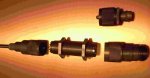
Connect the ground wire to the base of the antenna with one of these:

https://www.amazon.com/Workman-Lightning-Arrestor-Base-Antennas/dp/B01LYK5TU5
https://www.amazon.com/dp/B00427MQKE

The coax shield should also be grounded at the point it enters your house. The ground rod for this should be close to the coax entry point, and the entry point ground rod, the mast ground rods, and the ground rod(s) for your house electrical system should all be connected with minimum #6 wire.

Also, your J-pole antenna is way too close to the antenna next to it. The antennas are going to interfere with each other that close together. Ideally, you'd want at least 1/2-wavelength of the lowest frequency separation between them, but a full wavelength is even better. Depending on the power level involved, it's possible to fry the RF input amplifier in one radio if a TX antenna is too close to the RX antenna. Even if you don't fry a radio, separating the antennas will cut down on desense during transmit.
 

SpugEddy

Member
Premium Subscriber
Joined
Oct 4, 2015
Messages
438
Location
Camden County South Jersey
OK. So a grounding I must go. Not a real problem.
SINCE.... you also mentioned the close proximity of the
2 antennas, I've been suspicious of this being a problem
for a while. I've been waiting for a nice day so I can get out
and move the J Pole to the front of the shack using the same
mounting configuration. That will give me a 14' separation since
the shed is 12'x14'. That will give me chance to get the tape and
all of the weatherproofing off and ground it the "right way"

As for the A-99 (that is the 2nd antenna) I know that is properly
grounded. It's almost never used anymore. I mainly use it for
my SDR when I'm bored and listening to the Philadelphia
airport. I'm so close to the airport that a paper clip would probably
do fine, but the A-99 seems to do a great job.

I can't tell you how much I appreciate all of the help and info.
 

SCPD

QRT
Joined
Feb 24, 2001
Messages
0
Location
Virginia
SpugEddy, let me say first off that its neat you are a curious experiment‘r. :)
That said, let me throw out some ideas to consider.
.
First, if you want to seriously construct antennas, you are going to need some sort of standard to compare your designs against. Otherwise you’ll never really know just how good-or bad, each one is. To this end I suggest you build yourself a solid quarter wave ground plane-- for UHF that will be easy, but do it ’by the text book’- for after all it will become your ’lab standard.” I would suggest- and this is just a suggestion, mind you- but a similar one I use all the time in designing- --- a 12 inch diameter circle of ¼” aluminum with a centre hole- thru this hole a double ended SO-239 passes. You can now attach a quarter wave whip made from a PL-259 connector, and your feed cable to the other side. Use the best cable you can afford, preferably something large, like RG8, and make your PL-259/cable connections the best solder jobs you’ve ever done. I’m being serious: the better everything looks professionally, the better will be your ’standard.’
.
Now mount this as high, and in the clear of everything as possible. If, as suspect, you are interested in vertical polarization the mounting orientation is a given, though remember you can also mount this horizontal too, for other tests.
You now have a standard- a “Zero Gain” antenna- to compare your exotic designs against. Until you find that “magic“ configuration, this antenna may surprise you as the best one for what you want- for you can do far worse than a simple, clean quarter wave.
_________________________-----
.
On a different note, you mentioned RG/58 and another 72 ohm cable in conjunction with constructing a collinear array. Did I read that correctly?… Well, you can mix/subsitute them-- at your Peril! Different cables exhibit different velocity factors- vary the cables from the designer’s parameters may give you a less than desirer’d radiation patterns, etc. Even though you’re getting good SWR readings, your gain may be ‘naught.…’
.
But experiment away! :)
.
.
……………………..CF
 

SCPD

QRT
Joined
Feb 24, 2001
Messages
0
Location
Virginia
...........And I forgot this-- make your connections to this standard antenna also as 'clean' as possible-- meaning no tapping off points for grounds,no lightning arrestors, no spiced-in jumper cables- etc. Just your SWR meter, and temporary at that.
.
Oh,do I hear the howls!.. no lightning protection..!?
.
.... No, leave out all that clutter- just do your testing when its safe, and take it down when not in use. If you decide this is the best antenna, then do all the right stuff and static suppress it...;)
.
.................CF
 

KC4RAF

Member
Joined
Sep 30, 2006
Messages
1,579
Location
Davenport,Fl.- home to me and the gators and the s
Agree with CF. For experimenting, you leave out lightning arrestors and other devices. It is for experimenting and this is temporary for testing. Once the results are in and a permanent location is set, then the other devices may be put in place.
When experimenting and testing, these can influence the out come of a test.
 

SpugEddy

Member
Premium Subscriber
Joined
Oct 4, 2015
Messages
438
Location
Camden County South Jersey
Nice post(s) Coyote. I never considered a control. Why? I have no idea.
It makes total sense after somebody "turns on the lights"
This little guy that I have here (the DIY 1/4 wave) is built pretty tough.
It's not just an SO-239 with copper wire or hangers. I built it using a plate
to mount the SO-239 onto and then used some stronger aluminum rod
for the radials. So, when I get it fine tuned I'll use that as the control or
I can always use the dipole that I made which is also pretty sturdy. For the
dipole I used short telescoping transistor radio antennas so I can
use it on a few different bands.

One question though. I "think" I get your 12" aluminum plate idea. I'm
trying to picture it in my head but, my head can be a dangerous place.
Do you have any pix of this setup?
 

majoco

Stirrer
Joined
Dec 25, 2008
Messages
4,315
Location
New Zealand
Wikipedia...

The J-pole antenna, more properly known as the J antenna,[1] was first invented by Hans Beggerow in 1909 for use in Zeppelin airships.[2] Trailed behind the airship, it consisted of a single element, one half wavelength long radiator with a quarter wave parallel feedline tuning stub.

The J-pole has no ground connection at all, the two parallel bits at the bottom are a matching stub, the bigger bit at the top is a half wave radiator.

The "Slim Jim" has no ground connection either, it's mounted on a bit of PVC pipe. I made mine totally on a length of PVC pipe 32mm in diameter. Made a dummy one first to find the sweet spot then reassembled into the pre-drilled pipe. Works a treat just mounted on a wooden fence post.

I have never got my head around those copper pipe J-Poles where a copper stub extends below the matching section and it used as a mounting post - surely the lower section then affects the radiation pattern - you end up with two grounds - one through the coax and one through the pole.

Quote by W9BU, this post #2:
Is the mast metal? If so, it is de-tuning the Ed Fong J-pole. J-poles are an end-fed half-wave fed with a quarter-wave transformer (the dual-element portion of the J-pole at the bottom of the antenna). If anything metallic gets in the field of the transformer, it upsets the action of the transformer.

The beauty of the Slim Jim is that it pokes it's signal towards the horizon, not up in the air, that is where it gets its "gain" from. If you can, get hold of a old book called "Out of Thin Air" originally published in 1981 - in there is the original article by Fred Judd G2BCX. He shows vertical and horizontal plots of the radiation pattern that he found in his experiments.

Quote by dsalomon, this post #9:
One more difference between 1/4 wave, j-pole and slim jim antennas is the takeoff angle. Typical takeoff angles are:

1/4 wave antenna: 25'
j-pole: 20'
slim jim: 8'

We can't all be wrong, but to quote my old boss;

"One test is worth a thousand opinions"!
 
Last edited:

SCPD

QRT
Joined
Feb 24, 2001
Messages
0
Location
Virginia
Eddy, here is a detail of the double end'd SO-239 connector-- my guys tell me its more properly called a 'bulk head pass-thru".. but be that as it may....;) Also in there are two N connector adapters- (we use N connectors universally) and a PL-259 lab constuct'd antenna.
.
The ground plane disk you will have to imagine... the one I was thinking of using is 50' up on a tower right now, and I can't get anyone to climb up there for a pix'ur.
.
..................CF
 

Attachments

  • A- Connectors.jpg
    A- Connectors.jpg
    46.9 KB · Views: 438

majoco

Stirrer
Joined
Dec 25, 2008
Messages
4,315
Location
New Zealand
...and once you've made your 'reference antenna' you ideally need a 'reference station' - one that is preferably not very strong so you can hear some background noise. You should be able to make comparative judgements based on the increase or decrease of the noise. I use the ATIS from our local airport - he's only about 12miles away but there's a ridge in between me and him. Fortunately as well as a couple of BCT8 scanners and a Yaesu VR5000, I have an old but good Icom R7000 with a calibrated S meter so I don't have to make a 'guesswork' analysis.

CF - I don't really see the need for a disk, just four radials bent down a bit works well. If the disk is flat, the impedance is more like 75ohm although that won't matter a hoot for reception.

Oh, I see - NM for Coyotes and CO for Frostbite - nice :)
 

SpugEddy

Member
Premium Subscriber
Joined
Oct 4, 2015
Messages
438
Location
Camden County South Jersey
Don't know why my reply never posted.
But I see the picture now Coyote. The plate
is mounted between the 2 nuts on the bulkhead.

Thank you.
... And still pluggin away Majoco.
Now I'm just playing around with another antenna
build just out of pure boredom. I always need something
to do and building stuff is what I do best. After looking around
for the past couple days, I'm still thinking about the Arrow Open Stub
J Pole antenna. It looks like it could be a fun build. Just having a
tough time translating the info and measurements from the copper
pipe version to the aluminum model with 3 elements. I would
only want the 2 element version for 460-470 but can't for the life
of me figure out the proper element length and spacing.
 

SCPD

QRT
Joined
Feb 24, 2001
Messages
0
Location
Virginia
I agree, Majoco, that the aluminum disc is a tad over-kill- I was going for perfection :). I have a machine shop here at work that turns out my little designs- each a work of art; some, just beautiful to look at.
And too, a ground plane at a 90 degree angle to the radiator isn’t the best for a 52 ohm coax match - but I am usually looking at radiation patterns, not impedence numbers. And the use of radial wires that can be varied, as you said, will be more than adequate.
.
You made an excellent point I neglected completely-- a control’d signal source.
.
Again, in my work and I have a few other toys to play with than the average ham- For my controls I often use one of our mountain top sites where I can connect a HP signal generator into a variety of reference antennas. I can then vary the frequencies, and power (from microwatts on up)…. I was trying to think of a similar ham scenario to use- perhaps listening to a popular repeater and inserting attenuators… or tuning into a ham propagation beacon- if one is available in the area? I am sure inventive minds can come up with other (legal) ham band signal sources.
.
__________________________________
.
You brought a smile to my face with my “Coyote Frostbyte‘ and NM/CO connection-- I like it !
.. I never thought of my name like that.
Actually, its my tactical callsign at work- our department gives each other fun monikers to use on the air, (for instance, my friend and chief engineer is known as “Barbie“- I let you guess why ;) )
.
In the early years I was quite adapt at scrounging equipment from various agencies- my boss knew he could send the “Coyote” out and she’d bring back Goodies. The name stuck. Years later, in an ill fated attempt with an antenna project high above the Arctic Circle, I nearly frozen my team "to death !"- their words- not actually. It was close enuff, however, that they gave their boss her surname…….. I have been “Coyote Frostbite” ever since……………. :)
.
.
…………………….CF
 

majoco

Stirrer
Joined
Dec 25, 2008
Messages
4,315
Location
New Zealand
I have a machine shop here at work that turns out my little designs- each a work of art; some, just beautiful to look at.
Unfortunately since retirement I have moved away from my old workplace and no longer have access to the radio, test equipment or instrument workshops and all the manufacturing areas that go with an airline.
I was in the calibration section so had all the test equipment you could shake a stick at, mostly a few levels up from the general use stuff. Consequently before retirement I made sure all my personal gear was up to scratch! I recently acquired an HP 3586a SLM for a pittance non-working but the defects were trivial so I do have a good signal source on HF, now I'm looking for a 3458a!
 

majoco

Stirrer
Joined
Dec 25, 2008
Messages
4,315
Location
New Zealand
Well, Spug, I looked at the Arrow design and I notice that the mid-length element with the S-239 on the bottom is insulated from the cross piece - I don't know how they achieve the correct matching point unless there's an adjustable shorting piece inside the tube - seems a bit over-engineered to me - nicely made though out of good stainless too. Also the mast clamp doesn't appear to be insulated and as we've discussed before, that will affect the polar diagram, although I notice some pics say 'mount on a fibreglass or wooden pole'.

Likely that you won't be able to reproduce it and get good results without a great deal if trial and error. I've never made a two-frequency J-pole but as the frequencies are harmonically related I'd be inclined towards the 2metre version working adequately on 70cms anyway.
 

jonwienke

More Info Coming Soon!
Joined
Jul 18, 2014
Messages
13,409
Location
VA
The arrow J-pole is a reasonably good design. I've installed one for a friend and it was under 1.5:1 SWR throughout both .7 and 2-meter ham bands. The middle piece is driven--it acts as the short piece of the J-pole on 2 meters and the long piece of the .7-meter J-pole.

From a material and construction perspective, the Arrow is top-notch.
 

SpugEddy

Member
Premium Subscriber
Joined
Oct 4, 2015
Messages
438
Location
Camden County South Jersey
Looks nice and sturdy to me. The plans I found call for
3/8" solid aluminum rod and 1/4" thick aluminum L-Bracket.
That's why I inquired. Again, boredom is drawing me into
building one of these antennas. Taking my time and doing a nice
job, I could stretch this out to 2 days. It will most likely be built,
tried, tested, and then tossed into the pile with the others that I
made. As for my Ed Fong, it's up and staying up until the weather
breaks and I can move the whole mast to the front of the shack. If
one of the builds work out nice with good performance, then it will
become the used antenna replacing the one up now. If none are up to
snuff, then I'll just buy a better antenna this time.
 

NC1

Member
Joined
Feb 8, 2014
Messages
736
Location
Surry County, North Carolina
Post pics of your install, including how the antenna is grounded. I have a Fong J-pole, and while it may not be the absolute best out there, it is a decent antenna that should perform better than what you're describing.

Slim Jim antennas are NOT to be grounded. That is your problem right there.

Rather than give an explanation, here is a link that gives full and complete instructions for installation and construction of a Slim Jim.

SLIM JIM ANTENNA PROJECT

Hope that helps.
 

prcguy

Member
Premium Subscriber
Joined
Jun 30, 2006
Messages
16,903
Location
So Cal - Richardson, TX - Tewksbury, MA
J-pole antennas including the slim jim have very poor decoupling from the antenna to the coax and its recommended to use an effective choke near the feedpoint. You can wrap 3 turns of coax around a #43 mix ferrite clamp on bead as a starter.

With a good choke at the feedpoint the antenna will be fairly immune to grounding anywhere below the choke.
prcguy


Slim Jim antennas are NOT to be grounded. That is your problem right there.

Rather than give an explanation, here is a link that gives full and complete instructions for installation and construction of a Slim Jim.

SLIM JIM ANTENNA PROJECT

Hope that helps.
 

NC1

Member
Joined
Feb 8, 2014
Messages
736
Location
Surry County, North Carolina
With a good choke at the feedpoint the antenna will be fairly immune to grounding anywhere below the choke.
prcguy

Are you speaking from experience, or theory? I have absolutely no idea where you got that information, could you please provide a link? Every design I have seen says not to ground these type of antennas.

Maybe they are wrong, I do not know. But, if you follow the link below it clearly states - IN BOLDED CAPITAL LETTERS - (and I quote):

NOTE: NO PART OF THIS ANTENNA SHOULD BE GROUNDED!

So, that would indicate that his experiments and results had lead him to that conclusion, and to make a HUGE point of making sure those who install this antenna do NOT ground it - probably because grounding it results in extremely poor performance, which is why people say they suck (they grounded it!).

Here it is again in case you did not look at it the first time.
SLIM JIM ANTENNA PROJECT
 

nd5y

Member
Joined
Dec 19, 2002
Messages
11,907
Location
Wichita Falls, TX
So, that would indicate that his experiments and results had lead him to that conclusion, and to make a HUGE point of making sure those who install this antenna do NOT ground it
Or maybe he just doesn't know anything about antenna and transmission line theory and lighting safety.

Have you ever seen j-poles or slim jims used by anybody besides hams?
Ever wonder why none of the commercial antenna manufacturers (past of present) like Decibel, Antenna Specialists, Sinclair, Telewave sell j-poles or slim jims?
 

NC1

Member
Joined
Feb 8, 2014
Messages
736
Location
Surry County, North Carolina
Or maybe he just doesn't know anything about antenna and transmission line theory and lighting safety.

Well, every single site that has plans for building them says not to ground it. I guess they are all wrong?

So, you are going on theory?
Or did you actually build one and got excellent results with grounding vs not grounding?

I'm sure this fatal flaw you claim would have been noticed by someone in the last 20 years these plans have been around, and would have been corrected.

My money is on the guy who designed, built, and tested it. :)
 
Status
Not open for further replies.
Top