nd5y
Member
All I'm saying is if it wasn't a poor design you would see them in commercial installations.

All I'm saying is if it wasn't a poor design you would see them in commercial installations.
Are you speaking from experience, or theory? I have absolutely no idea where you got that information, could you please provide a link? Every design I have seen says not to ground these type of antennas.
Maybe they are wrong, I do not know. But, if you follow the link below it clearly states - IN BOLDED CAPITAL LETTERS - (and I quote):
NOTE: NO PART OF THIS ANTENNA SHOULD BE GROUNDED!
So, that would indicate that his experiments and results had lead him to that conclusion, and to make a HUGE point of making sure those who install this antenna do NOT ground it - probably because grounding it results in extremely poor performance, which is why people say they suck (they grounded it!).
Here it is again in case you did not look at it the first time.
SLIM JIM ANTENNA PROJECT
A stock J-pole will be influenced by grounding or attaching to a metal support pipe. etc. This is because these antennas have lots of common mode currents riding on the coax because of poor decoupling. If you decouple the J-pole with proper use of ferrite, then whatever is below the ferrite has little influence on the antenna.
I've done this and it works on J-poles and many other antennas that have feedline decoupling problems. This is not something I made up, its common knowledge. Most likely the so called designer of the antenna was not up on common mode currents and how to address them.
prcguy
My money is on the guy who designed, built, and tested it.
")
Slim Jim antennas are NOT to be grounded. That is your problem right there.
Rather than give an explanation, here is a link that gives full and complete instructions for installation and construction of a Slim Jim.
SLIM JIM ANTENNA PROJECT
Hope that helps.
I have been following the discussion on these antennas -and several things strike me. First off, both the ‘J’ design and the “Slim Jim” are not Beginner’s Antennas-- especially! the later. I just read G2BCX’s article; I understand the theory behind this antenna; at the same time I can also see that building one by a neophyte is fraught with pit falls. Mechanically it is an awkward design. Constructing it to be stable enuff for long term out-of-doors would be challenging, there is no provision to ground it, the feed points are vague, and the use of twinlead feedlines makes me cringe (tho coax can be used) - these are among the detractors I found.
.
ND5Y sum’d it up: ….
“All I'm saying is if it wasn't a poor design you would see them in commercial installations”
.
In fairness to G2BCX, I sure his design works well for him, but there is a vast difference between the lab and the field… which brings me to point number Two--
.
SpugEddy, I am going to step you aside - for after all you were the one asking the original questions. I’m telling you that these types of antennas may be in your future, but steer clear of them for now. Aside from the obvious quarter-wave ground plane, here are a few of my suggestions if you still want to build-
.
Try your hand at that coaxial collinear vertical- but do it by the book- no substitutions of coax’s, etc….. or try some of the other phased section collinears… the books are full of them. The nice about these- you can assemble them in fiberglass or PVC pipes to make them weather proof...and they can be grounded
One of my favorites- the fold’d dipole- they are mechanically as tough as bricks. You can stack them in phase for additional gain, if you wish, they are easy to build and tune….. And going back to the commercial standard analogy- look at any 2-way tower- they are the antennas of choice.
.
Personally, I like the design of the Ringo Ranger.. ..not only for their simplicity of design, but ease of tuning- not to mention their inherent static suppression- everything is at DC ground. In the field we use similar designs all the time on 400-420MHz. If you feel so inclined, they are easy to duplicate.
.
What I am trying to get across is to avoid the anecdotal stories of how great an antenna is to one particular person as compared to something else. Antennas are one highly charged subject for hams… so approach them like a scientist,--- for remember, you can get a brine soaked piece of string to radiate RF- and some might laud it to the heavens as the best thing since sliced bread.
.
…………….CF
.
.
If I get a few moments in the next couple of weeks I might put together a UHF “Slim Jim” design and run it thru a few lab tests of my own- stay tuned…….
Spugeddy - it's been an interesting discussion - let us know what you finally decide. Hope we haven't overwhelmed you!
.
(I hope I didn't come across as too much of a lecture'r...smiles)
.
............CF
All I'm saying is if it wasn't a poor design you would see them in commercial installations.
The J-Pole revisited.
I have a few questions for anybody who is able to help
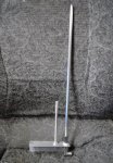
Below is a pic of the "official" Arrow J-Pole antenna.
Lets say, from left to right the elements are "A" "B" and "C"
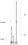
Then a pic of my homebrew J-Pole
Being a single band antenna, my build eliminates the long
element C. (I'm only using it for UHF) I changed the lengths
accordingly.
A (long element) = 18½"
B (short element) = 6"
What is each element called? What does it do?
Do I need element C?
Do my lengths look correct?