• To anyone looking to acquire commercial radio programming software:

    Please do not make requests for copies of radio programming software which is sold (or was sold) by the manufacturer for any monetary value. All requests will be deleted and a forum infraction issued. Making a request such as this is attempting to engage in software piracy and this forum cannot be involved or associated with this activity. The same goes for any private transaction via Private Message. Even if you attempt to engage in this activity in PM's we will still enforce the forum rules. Your PM's are not private and the administration has the right to read them if there's a hint to criminal activity.

    If you are having trouble legally obtaining software please state so. We do not want any hurt feelings when your vague post is mistaken for a free request. It is YOUR responsibility to properly word your request.

    To obtain Motorola software see the Sticky in the Motorola forum.

    The various other vendors often permit their dealers to sell the software online (i.e., Kenwood). Please use Google or some other search engine to find a dealer that sells the software. Typically each series or individual radio requires its own software package. Often the Kenwood software is less than $100 so don't be a cheapskate; just purchase it.

    For M/A Com/Harris/GE, etc: there are two software packages that program all current and past radios. One package is for conventional programming and the other for trunked programming. The trunked package is in upwards of $2,500. The conventional package is more reasonable though is still several hundred dollars. The benefit is you do not need multiple versions for each radio (unlike Motorola).

    This is a large and very visible forum. We cannot jeopardize the ability to provide the RadioReference services by allowing this activity to occur. Please respect this.

Galaxy saturn 11 meter

N1EXA

FT8 Huntin Mudd Duck on the deep end of the pond !
Joined
Mar 3, 2022
Messages
318
Location
Acushnet Heights New Bedford MA - GRID FN41 mp
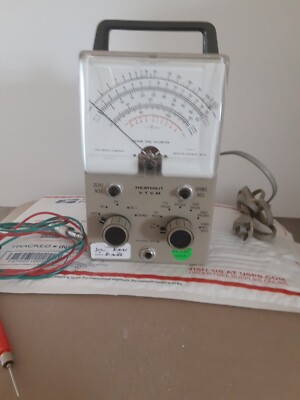
What you need to work on this radio is an old school Heatkit Tube Voltmeter and a home brew RF probe.

images
s-l400.jpg


What happens with these radios is guys want more power but the radio is only designed for 10 watts AM say 20 SSB

and if you go to page 29 in the manual you will see C166 (560pf) off the Final amp - Those vaporise over time and high power

so you have to put a higher voltage on or take 2 -330pg and parrellel them up to handle the stress.

I seen so many cbers swap finals and say it does not work. thats where the tube voltmeter and probe come in. you cant trouble shoot

stuff with a Chinese DVM other than basic AC line power DC Voltages and Current and resitsors removed from the circuit.

I had to put a bigger transistor on the 8 v TX switch and the Transistor feeding the voltage to the Finals too.

There is a page on the web that i cant find now but shows the 2 ceramic caps that are added to the finals for tuning.

Bottom of the Circuit Board ! ( Look )

Hope fully the original tech put them back where they were. Its best to take pictures before unsoldering anything because you may find

out that it was OEM work at the factory and not the golden screw driver.

Pete N1EXA
 

109base

10-9 base
Joined
Jun 8, 2025
Messages
20
what ever he did who ever did the soldering did not have a clue! It looked like he used one of those weller 1000 watt soldering guns every thing that was soldered was burnt n cold! Not one solder spot was clean!
 

N1EXA

FT8 Huntin Mudd Duck on the deep end of the pond !
Joined
Mar 3, 2022
Messages
318
Location
Acushnet Heights New Bedford MA - GRID FN41 mp
what ever he did who ever did the soldering did not have a clue! It looked like he used one of those weller 1000 watt soldering guns every thing that was soldered was burnt n cold! Not one solder spot was clean!
At least he soldered the parts - I got a guitar amp and the guy said it didnt work .
When I opened it up he used a hot glue gun on all the parts he swapped because he didnt have soldering iron.
at some point on the PCB he added 2 diodes swapping the polarity Ill assume to make a distortion Circuit?
Well at least i didnt have to trouble shoot problems because everthing hot glued was obviously wrong.
After a few hours of work It made noise again and did what it was intended to be - A crappy Guitar amp.

Your Just going to have to go though everything on the saturn with the manual and besides all the bad solder joints
you will have to do a basic calibration using the manual to see if the Golden Screw Driver was used.

Pete N1EXA
 

109base

10-9 base
Joined
Jun 8, 2025
Messages
20
Yea its my next step after i get this part in today im gonna start by checking voltages making sure nothing is messed with before go any further! With this radio im assuming the worst on everything but hoping for the not so bad lol
 

109base

10-9 base
Joined
Jun 8, 2025
Messages
20
Well got to a point to plug in the radio! It has several things going on! First almost just like it was before i touched it but! Now the freq counter is stable! But shows channel 1 as 28,031. Ok and as before it has that tone that oscillates no matter what with no receive no transmit. Still. My first instinct im gonna test the pll chip to see if all the volts are correct! Also it almost appears like the transmitter is keyed up even though the receiver is not shut down! Like they are both keyed at the same time if thats possible! It kinda looks like the transmit light is on. But nothing on the meters! Like i said this radio i think several issues!
 

slowmover

Active Member
Joined
Aug 4, 2020
Messages
3,558
Location
Fort Worth
LOL. that's something! I don't think I've ever seen hot glue used in lieu of solder. I've seen "a lot" but that's a new one!

Memorable enough to offer someday as tongue-in-cheek advice. ‘Cause somebody already been there and done that.

Is cyanoacrylate “super glue” a conductive substitute for solder? also has legs, thereby.

.
 

N1EXA

FT8 Huntin Mudd Duck on the deep end of the pond !
Joined
Mar 3, 2022
Messages
318
Location
Acushnet Heights New Bedford MA - GRID FN41 mp
Well got to a point to plug in the radio! It has several things going on! First almost just like it was before i touched it but! Now the freq counter is stable! But shows channel 1 as 28,031. Ok and as before it has that tone that oscillates no matter what with no receive no transmit. Still. My first instinct im gonna test the pll chip to see if all the volts are correct! Also it almost appears like the transmitter is keyed up even though the receiver is not shut down! Like they are both keyed at the same time if thats possible! It kinda looks like the transmit light is on. But nothing on the meters! Like i said this radio i think several issues!
OK
You need to open up that service Manual and go to the 8volt circuit driving the transmitter sound like they poped the transistor that runs the circuit.
I can't evenforce enough that you need to go through and check your service manual and
Check the circuits on pages 28 29 and 31 in the repair tip section.
TR38 I replaced with a big heat sinked PNP transistor on extended leads off the PCB the 2SB525 is not robust enough.

Pete N1EXA
 

109base

10-9 base
Joined
Jun 8, 2025
Messages
20
Ok your spot on and im one step ahead! The one part i was waiting on was tr38. It was missing i said thats odd why would they remove that! Thats why i had to wait to start digging figured wouldnt do anygood trouble shooting if parts were missing so i got it installed it ! Then i started at tr41 realized low voltage! Only 6 volts on e & b pins So then i went to the begining of that area where the power first starts at the 4 pin plug and checked for my 8 volts! It was working! Then i next checked tr36 and voltage stopped! So i ordered new for tr36 tr37 tr39 tr40 tr41. I figure will be good to have on hand cause im gonna bet the rest might be weak!
Tonight im also gonna check the diods 76 77 78 79 to see they appear to be good!
 

109base

10-9 base
Joined
Jun 8, 2025
Messages
20
Im trying to learn my test equip i had to switch to my standby vtm my new one i bought was a cheap one but im i guess not setting it right i did not like how it was working! I do alot of electrical on cars n motorcycles so i used my general use vtm witch seem to give me good readings!
 

109base

10-9 base
Joined
Jun 8, 2025
Messages
20
I do have a question since im not familiar with this radio! I found this odd for a cb radio! Ok it has the power toggle switch! When i flip that on the meters light up but thats all that happens! No sound nothing! Intill you turn the squelch knob it clicks like a on off switch then the radio starts making sound! Is this normal?
 

K9KLC

Member
Premium Subscriber
Joined
Mar 31, 2007
Messages
1,206
Location
Southwest, IL
I do have a question since im not familiar with this radio! I found this odd for a cb radio! Ok it has the power toggle switch! When i flip that on the meters light up but thats all that happens! No sound nothing! Intill you turn the squelch knob it clicks like a on off switch then the radio starts making sound! Is this normal?
Are you pulling on it or turning it CCW?
 

N1EXA

FT8 Huntin Mudd Duck on the deep end of the pond !
Joined
Mar 3, 2022
Messages
318
Location
Acushnet Heights New Bedford MA - GRID FN41 mp
I do have a question since im not familiar with this radio! I found this odd for a cb radio! Ok it has the power toggle switch! When i flip that on the meters light up but thats all that happens! No sound nothing! Intill you turn the squelch knob it clicks like a on off switch then the radio starts making sound! Is this normal?
That Squelch Knob when turned all the way to the 7 Oclock position and clicks turns off the radio and turns on the PA Circuit.
Dont ask why you need a PA circuit on a base station but that oprion is there.
You mention you have a power toggle switch instead of a push button - Thats the Early version of the Galaxy Saturn Base.

Ill say when you study the Service manual understand it written for the newer model. Pretty much everything is the same
but look at page 31 under tr36 AND tr38 There are 2 different pin outs for the Transistors. Yah got to be real careful
playing with this stuff there are modes here and there that people dont read or see.

Pete N1EXA
 

K9KLC

Member
Premium Subscriber
Joined
Mar 31, 2007
Messages
1,206
Location
Southwest, IL
say when you study the Service manual understand it written for the newer model. Pretty much everything is the same
Maybe this explains the difference in the PA switch. I never saw one where at 7 it was the PA only the pull one. Guess I never saw it set up an order one. I don't mess with them any more but always good to learn.
 

N1EXA

FT8 Huntin Mudd Duck on the deep end of the pond !
Joined
Mar 3, 2022
Messages
318
Location
Acushnet Heights New Bedford MA - GRID FN41 mp
Interesting all the ones I have seen you had to pull it to activate the PA.
There are quite A few versions of the Saturn Base and thier alter egos's over the years. The manual Link I posted gives a good
overview of the rig but dont be surprised when you see under the hood the echo board is different or Capacitors have different Values
then stated.

Like my Browning Golden Eagle MK 3 - For the production run they made quit a few sub models I alway love when somebody posts
a schematic of the reciever or transmitter but never say what year or SN # run it applies to.

I bought a service manual on ebay - Guy claims its the Ultimate Browning Eagle Book - Well its pretty obvious he grabbed what he could
to print but dont think he really serviced any or he focused on the one he owned.

Pete N1EXA
 
Last edited:
Top