Hi, I have two antennae. One is a reference, and the other is DUT. I have to use Gain Transfer Method to find AUT gain. For this, i have used a reference horn antenna in the chamber and measured s21. then I put DUT on and measured S21. Now my question is, "How can I convert this S21 into received power?" I have to use this received power in the Gain formula to find gain. please HELP
- Forums
- Scanners, Receivers and Related Equipment Forums
- Antennas and Associated Hardware
- Scanner / Receiver Antennas
How to measure received power from s21 of antenna?
- Thread starter jawad231
- Start date
- Status
- Not open for further replies.
AB5ID
Member
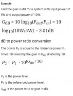
Once you had the difference in decibels from S21 you should be able to calculate the change in power ratio.
Here's an answer from chat GPT
"Convert dB to power
Formula to convert decibel change into power
To convert a decibel (dB) change into a power ratio, you View attachment 139749can use the following formula:
Power ratio = 10^(dB change/10)
This formula can be used to calculate the ratio of two power levels, where the dB change is the difference between the two levels expressed in decibels.
For example, if you have a power level of 10 watts (dBW = 10) and you want to calculate the power ratio when the level increases by 3 dB, you can use the formula as follows:
Power ratio = 10^(3/10) = 1.995
This means that the power level has increased by a factor of 1.995 or approximately 2 times.
Similarly, if the power level decreases by 6 dB, the power ratio can be calculated as:
Power ratio = 10^(-6/10) = 0.251
This means that the power level has decreased by a factor of 0.251 or approximately 1/4 times."

Last edited:
The way I see it you cannot determine "received power" at the DUT unless you know the power applied to the reference antenna and you know the gain of that antenna and the free space loss between antennas and the gain of the DUT. Or you could just measure the received power at the DUT with a power meter or spectrum analyzer with the first being more accurate. You would also want to use CW in this case as a modulated waveform from the test generator is usually not 100% duty cycle.
AB5ID
Member
This article might help.

 phanquocdat.wordpress.com

How To Measure Antenna Gain (Part 1) – Gain Transfer Method
September 8, 2010 Gain is one of the key specifications in antenna datasheets. It is defined as the ratio of the intensity of an antenna (usually in direction of peak radiation) relative to an isot…
Thank you for the reply. input power is -5 dBm, and the reference antenna gain is 19 dB. I have a network analyzer but i don't know how to measure power in VNA, and all the measurements are performed in anechoic chamberThe way I see it you cannot determine "received power" at the DUT unless you know the power applied to the reference antenna and you know the gain of that antenna and the free space loss between antennas and the gain of the DUT. Or you could just measure the received power at the DUT with a power meter or spectrum analyzer with the first being more accurate. You would also want to use CW in this case as a modulated waveform from the test generator is usually not 100% duty cycle.
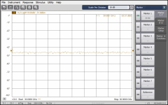
The VNA should measure power when not calibrated for S21, if you turn off cal it should show what the levels are across the trace and you might have to use markers to identify specific frequencies. Since the gain of the reference antenna will vary over frequency the power received at the DUT antenna will vary with frequency and so will the signal level at the connector on the DUT antenna.Thank you for the reply. input power is -5 dBm, and the reference antenna gain is 19 dB. I have a network analyzer but i don't know how to measure power in VNA, and all the measurements are performed in anechoic chamber
Do you have a power meter or spectrum analyzer? If so turn the VNA generator to a specific frequency CW no modulation then connect the power meter or spectrum analyzer to the DUT antenna. The received power out of the DUT antenna will be whatever you measure minus the cable loss that is between the DUT antenna and power meter or spectrum analyzer. A spectrum analyzer can also be off as much as a few dB and is not considered an accurate power measuring device but a power meter is.
AB5ID
Member
Is this a real world measurement you're going to make, or theoretical to answer a question?Thank you for the reply. input power is -5 dBm, and the reference antenna gain is 19 dB. I have a network analyzer but i don't know how to measure power in VNA, and all the measurements are performed in anechoic chamber
Ok... help me out here, if CW is 100% duty cycle, its just a RF carrier that is wider.... If you mean CW like morse code, wouldn't anything that is normally thought of as 100% duty cycle do ok (FSK etc.)... or do you mean just use a signal generator with a tone... like a 1Kz tone or something?The way I see it you cannot determine "received power" at the DUT unless you know the power applied to the reference antenna and you know the gain of that antenna and the free space loss between antennas and the gain of the DUT. Or you could just measure the received power at the DUT with a power meter or spectrum analyzer with the first being more accurate. You would also want to use CW in this case as a modulated waveform from the test generator is usually not 100% duty cycle.
It didn;'t help that the start of the thread was a little ambiguous to me. I thought the OP just meant comparing one antenna with another and switching between the two. Apparently were talking mini test range...
Thanks
Joel
AB5ID
Member
I think that is the question at hand. To me, it sounds like a question from a college course.I thought the OP just meant comparing one antenna with another and switching between the two.
Thanks
Joel
Your right, sounds like a college course thing. I should have assumed a test range when a "chamber" was mentioned, and S21 doesn't mean anything to me at all without further references.I think that is the question at hand. To me, it sounds like a question from a college course.
Thanks
Joel
CW in the RF measurement business is Continuous Wave, no modulation or "constant carrier". Signal generators used for Vector Network Analyzers or Scalar Network Analyzers use a specific pulsed modulation as part of the measurement system that is about 50% duty cycle and that will give wrong power meter readings. You can select CW for 100% duty cycle and then use power meters for precise power level measurement or a spectrum analyzer for a somewhat close power measurement.Ok... help me out here, if CW is 100% duty cycle, its just a RF carrier that is wider.... If you mean CW like morse code, wouldn't anything that is normally thought of as 100% duty cycle do ok (FSK etc.)... or do you mean just use a signal generator with a tone... like a 1Kz tone or something?
It didn;'t help that the start of the thread was a little ambiguous to me. I thought the OP just meant comparing one antenna with another and switching between the two. Apparently were talking mini test range...
Thanks
Joel
Just for the record, I spent most of my career doing RF and microwave measurements and while most babies had a plastic pacifier, I had an HP Spectrum Analyzer to suck on.
Thanks for the clarification, I have an old boat anchor type signal generator that can put out a continuous tone on the RF signal, I like to think of that as 100% duty cycle,CW in the RF measurement business is Continuous Wave, no modulation or "constant carrier". Signal generators used for Vector Network Analyzers or Scalar Network Analyzers use a specific pulsed modulation as part of the measurement system that is about 50% duty cycle and that will give wrong power meter readings. You can select CW for 100% duty cycle and then use power meters for precise power level measurement or a spectrum analyzer for a somewhat close power measurement.
Just for the record, I spent most of my career doing RF and microwave measurements and while most babies had a plastic pacifier, I had an HP Spectrum Analyzer to suck on.
There is obviously some differences on how terms are defined depending on what part of the radio area were talking about,
I'm thinking
CW can mean the constant carrier like in this case or morse code.
A beacon transmitting a CW id constantly would be considered 100% duty cycle
A RTTY station would be considered 100% duty cycle if it was always in the transmit mode.
How does MCW fit into this. I'm thinking 100% duty cycle for a constant on beacon, but RF test measurement would have it at 150%? correct?
Power supply wise, though, everything above should be rated for 100% duty cycle.
(Not being a wise AXX here, I just know different words mean different things depending on context, just trying to sort it out).
Thanks
Joel
G7RUX
Active Member
- Joined
- Jul 14, 2021
- Messages
- 672
In measurement activities CW only means continuous wave, no keying. MCW is typically keyed carrier with a single side and modulated tone so it can be heard without the need for a BFO, although sometimes it is full DSB AM for use with an even simpler receiver. This would not give 150% duty cycle, although the peak power would be more than the peak power of a carrier alone due to the modulation power, depending on how the modulation is achieved.Thanks for the clarification, I have an old boat anchor type signal generator that can put out a continuous tone on the RF signal, I like to think of that as 100% duty cycle,
There is obviously some differences on how terms are defined depending on what part of the radio area were talking about,
I'm thinking
CW can mean the constant carrier like in this case or morse code.
A beacon transmitting a CW id constantly would be considered 100% duty cycle
A RTTY station would be considered 100% duty cycle if it was always in the transmit mode.
How does MCW fit into this. I'm thinking 100% duty cycle for a constant on beacon, but RF test measurement would have it at 150%? correct?
Power supply wise, though, everything above should be rated for 100% duty cycle.
(Not being a wise AXX here, I just know different words mean different things depending on context, just trying to sort it out).
Thanks
Joel
A beacon continuously transmitting a Morse ID, for example, would not give 100% duty cycle but somewhat lower.
100% duty cycle of an RF signal would be key a transmitter with no modulation and put a brick on the key switch. Any type of amplitude or pulse modulation is less than 100% duty cycle. A beacon sending Morse CW is not 100% duty cycle unless you send an endless Daaaaaaaaaaaaaaaaaaaaaaaaaaaaa. MCW is not 100% duty cycle unless its FM mode and its keyed down forever. AM modulation would be less than 100% duty cycle. A pulsed radar can be just a few % duty cycle depending on pulse width and repetition rate. Any amplitude or pulse modulation will affect what a power meter reads unless its specifically set up to deal with amplitude modulation.Thanks for the clarification, I have an old boat anchor type signal generator that can put out a continuous tone on the RF signal, I like to think of that as 100% duty cycle,
There is obviously some differences on how terms are defined depending on what part of the radio area were talking about,
I'm thinking
CW can mean the constant carrier like in this case or morse code.
A beacon transmitting a CW id constantly would be considered 100% duty cycle
A RTTY station would be considered 100% duty cycle if it was always in the transmit mode.
How does MCW fit into this. I'm thinking 100% duty cycle for a constant on beacon, but RF test measurement would have it at 150%? correct?
Power supply wise, though, everything above should be rated for 100% duty cycle.
(Not being a wise AXX here, I just know different words mean different things depending on context, just trying to sort it out).
Thanks
Joel
Duty cycle of a transmitter is a different topic and usually refers to a safe amount of time it can be in transmit mode without overheating.
In measurement activities CW only means continuous wave, no keying. MCW is typically keyed carrier with a single side and modulated tone so it can be heard without the need for a BFO, although sometimes it is full DSB AM for use with an even simpler receiver. This would not give 150% duty cycle, although the peak power would be more than the peak power of a carrier alone due to the modulation power, depending on how the modulation is achieved.
A beacon continuously transmitting a Morse ID, for example, would not give 100% duty cycle but somewhat lower.
But the transmitter should be rated for 100% duty cycle for a beacon, right?
When the FCC talks about MCW, are they talking about cw with a single sideband or DSB (or both)? ,
I always thought it was DSB.
Thanks
Joel
Gotcha (I think) so my signal generator sending a 1Khz tone is 100% duty cycle.100% duty cycle of an RF signal would be key a transmitter with no modulation and put a brick on the key switch. Any type of amplitude or pulse modulation is less than 100% duty cycle. A beacon sending Morse CW is not 100% duty cycle unless you send an endless Daaaaaaaaaaaaaaaaaaaaaaaaaaaaa. MCW is not 100% duty cycle unless its FM mode and its keyed down forever. AM modulation would be less than 100% duty cycle. A pulsed radar can be just a few % duty cycle depending on pulse width and repetition rate. Any amplitude or pulse modulation will affect what a power meter reads unless its specifically set up to deal with amplitude modulation.
Duty cycle of a transmitter is a different topic and usually refers to a safe amount of time it can be in transmit mode without overheating.
MCW though is NOT 100% duty cycle, I really thought that it was. Like a continuous carrier that is modulated, but even when not being modulated, is still there.
The duty cycle of a transmitter for overheating purposes (and I assume power supply purposes) kind of relates to the same words meaning different things depending on context (like the rest of the English language).
Unless (and I assume this is correct) there is more misunderstanding on my part.
Thanks
Joel
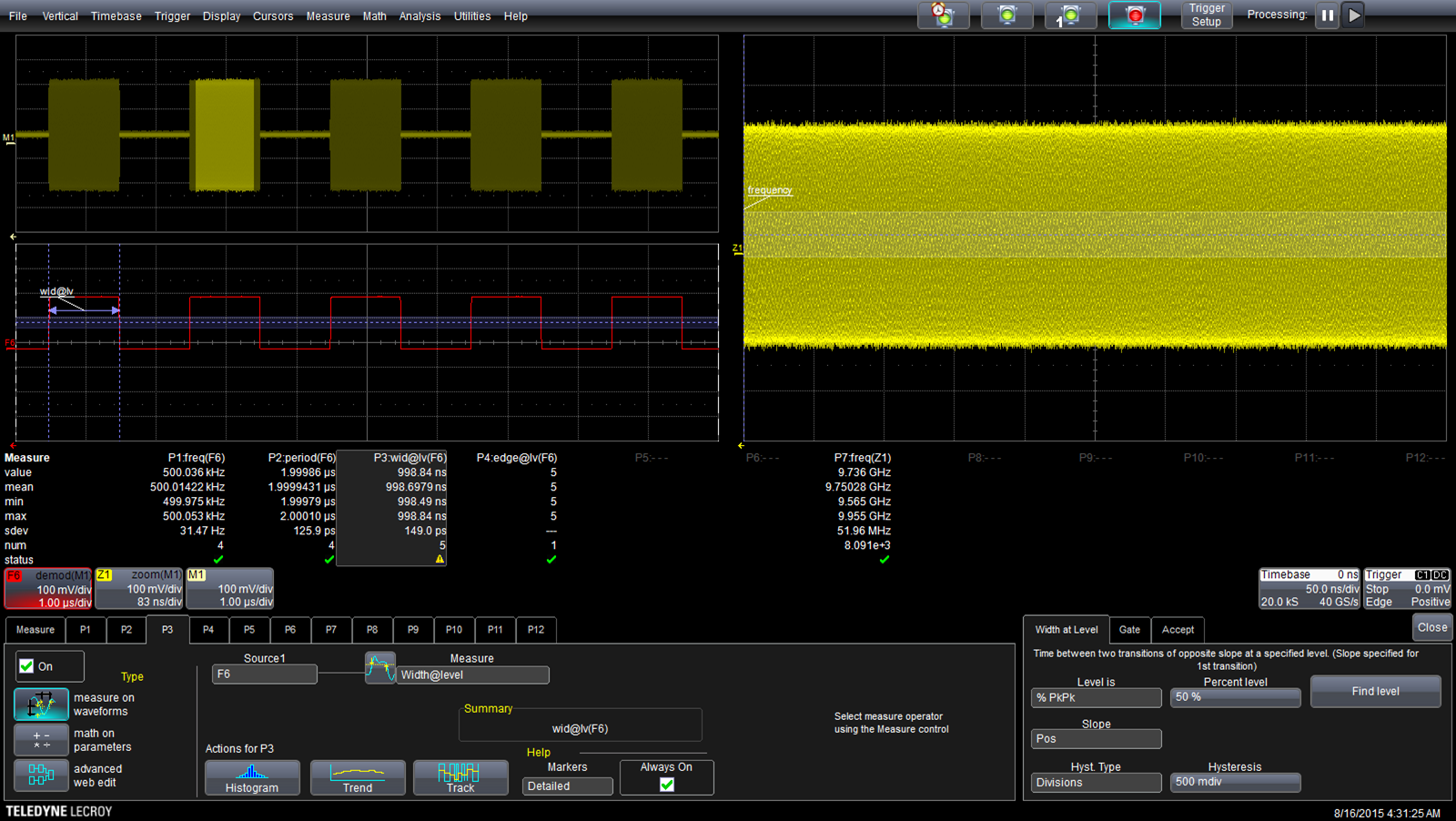
Looking at the picture below of an oscilloscope with different RF waveforms, the bright yellow one on the upper right would indicate a continuous wave carrier without modulation. That would allow a typical RF power meter to measure the level accurately. The yellow pulse modulated trace in the upper left corner is about 50% duty cycle and would cause an RF power meter to read about 3dB low because there is no RF present for about half the time. AM modulation would give a different result depending on depth of modulation and the transmitter characteristics.Gotcha (I think) so my signal generator sending a 1Khz tone is 100% duty cycle.
MCW though is NOT 100% duty cycle, I really thought that it was. Like a continuous carrier that is modulated, but even when not being modulated, is still there.
The duty cycle of a transmitter for overheating purposes (and I assume power supply purposes) kind of relates to the same words meaning different things depending on context (like the rest of the English language).
Unless (and I assume this is correct) there is more misunderstanding on my part.
Thanks
Joel

and power meter characteristicsLooking at the picture below of an oscilloscope with different RF waveforms, the bright yellow one on the upper right would indicate a continuous wave carrier without modulation. That would allow a typical RF power meter to measure the level accurately. The yellow pulse modulated trace in the upper left corner is about 50% duty cycle and would cause an RF power meter to read about 3dB low because there is no RF present for about half the time. AM modulation would give a different result depending on depth of modulation and the transmitter characteristics.

Thanks for going out of your way for this.
Thanks
Joel
No problem, people went out of their way to show me stuff and its good to pass things along.and power meter characteristics
Thanks for going out of your way for this.
Thanks
Joel
Hello,The VNA should measure power when not calibrated for S21, if you turn off cal it should show what the levels are across the trace and you might have to use markers to identify specific frequencies. Since the gain of the reference antenna will vary over frequency the power received at the DUT antenna will vary with frequency and so will the signal level at the connector on the DUT antenna.
Do you have a power meter or spectrum analyzer? If so turn the VNA generator to a specific frequency CW no modulation then connect the power meter or spectrum analyzer to the DUT antenna. The received power out of the DUT antenna will be whatever you measure minus the cable loss that is between the DUT antenna and power meter or spectrum analyzer. A spectrum analyzer can also be off as much as a few dB and is not considered an accurate power measuring device but a power meter is.
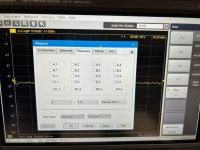
In keysight VNA I found this option for measuring power. is it the right option here?
hi it is real measurements for mm-wave band antenna 30 GHzIs this a real world measurement you're going to make, or theoretical to answer a question?
Attachments
- Status
- Not open for further replies.
Similar threads
- Replies
- 11
- Views
- 2K
- Replies
- 5
- Views
- 1K
- Replies
- 0
- Views
- 738
- Replies
- 18
- Views
- 2K


