I'm just a little confused. If you already have a "switched" source, then why would you want to run it through another switch? What are trying to power up?
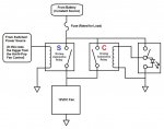
Here is an example of what we do for K9 vehicle exhaust fans. The fans are set to come on if the temperature in the car becomes too hot. This is automatic and is always on when the K9 Popper is active. Once it reaches a certain temp, the rear windows roll down, the exhaust fans turn on, the cars blue lights turn on and the officer receives a page that the temp in the car is too hot for his dog. A lot going on there, but that is the "switched" voltage side of the equation as it happens automatically without intervention from the officer.
For the "constant" power side of things, there is a switch that is wired in that can provide power to the fans if the officer so desires and is completely immune to the K9-Popper's status. The switch is also not under the load of the fan.
If the K9 Popper trigger goes high, then relay "S" will energize and the fan will pull power from the battery through the contacts of relay "S."
If the K9 Popper is not activated, but the officer wants to turn on the fans, then he uses the switch, which energizes relay "C" and therefore, pulls power from the battery through the contacts of relay "C."
Neither system is affected by the other.
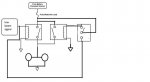
As you can see, the LED on our system only illuminates when the switch is active. If we had switches like yours, we could wire one LED to remain on when the car is running and then light another LED upon activation of the switch. We just don't have them on-hand.
As I said, this is just an example of what we do. It would help greatly if you told us what equipment you were trying to install.