LED-Toggle Wiring Question,Is this Do-Able?

Status
Not open for further replies.
Joined
Feb 3, 2009
Messages
2,078
Reaction score
20
Location
So Far Away....
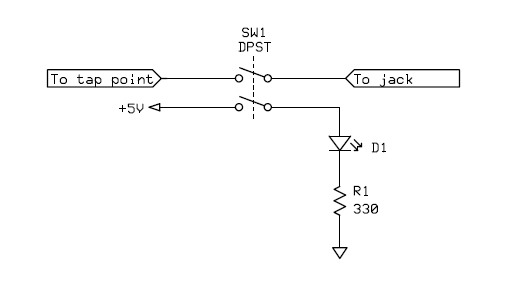
going over an idea for a On-Off toggle
to activate-deactivate a Disc Tap..complete with an LED indicator to show when the tap is hot..

looking at using a Negative as the -Hot- wire,,to close the circuit for the LED and the Ground for the tap
in one shot..

any thoughts on power feeding back thru the LED into the tap?..this seems to be my main concern,,if this is an issue its probably a wash unless i can score a ultra tiny relay of some sort..

Please refer to the cavemanish diagram we concocted..
 

Attachments

  • Photo-0017.jpg
    Photo-0017.jpg
    32.9 KB · Views: 565

Thayne

Member
Joined
May 1, 2002
Messages
2,145
Reaction score
11
I would just use a single throw double pole switch and not chance it. They are very common and not any bigger than single pole switches.
 

mancow

Member
Database Admin
Joined
Feb 19, 2003
Messages
6,943
Reaction score
1,136
Location
N.E. Kansas
The drawing is definitely not how I would do it. I agree with Thayne, use a double throw switch. One side controls led power and is isolated from the tap circuit.

Also, I would switch the tap center (hot) line not the ground. Leaving the ground unswitched won't cause any issues but leaving the tap line definitely could.
 

gmclam

Member
Premium Subscriber
Joined
Sep 15, 2006
Messages
6,518
Reaction score
692
Location
Fair Oaks, CA
Discriminator output and LED

any thoughts on power feeding back thru the LED into the tap?..this seems to be my main concern,
Yes.

A pseudonym for discriminator is demodulator. In FM receivers, the discriminator provides no output when the input signal is not changing. As the input changes frequency, a voltage is output to represent that change. So for example; you could have a frequency modulated 455kHz signal at the input, and the discriminator outputs the signal which was modulating the input; typically audio.

What is the output impedance of the discriminator? Can it provide enough current to drive an LED? Can it drive the LED while still providing enough signal to the intended load? What is the voltage of the discriminator output (nominal and maximum)? Is it enough to overcome the voltage loss through the LED?

Once you're past all of that. Do you realize that there is "always" "audio" being output from a discriminator? Remember these taps are before the squelch circuit of our scanners.

In other words; I don't think it will work. Additionally, if you plan to put power on the LED, that voltage could damage the device driving the discriminator.

Ironically, if what you want is a light to see when audio is present, you'd be better off driving that from the speaker connection. Add your discriminator tap and connect that to the computer as per usual. Disconnect the speaker and connect your LED with current limiting resistor there. When the squelch breaks, the light comes on.
 

DonS

Member
Joined
Jun 17, 2003
Messages
4,099
Reaction score
-2
Location
Franktown, CO
Nitpick: the resistor doesn't "step voltage down". It limits current through the LED (EDIT: as suggested by gmclam in his reply!).
 

n5usr

Member
Joined
Aug 10, 2007
Messages
596
Reaction score
2
Location
Bethany, OK
im looking at teh SPDTs can you post a link to the style switch your referencing?

thanks!

You want a "DP" (double pole) switch. It can be either "DT" (double throw) or "ST" (single throw). Thus, "DPST" or "DPDT".

Double pole means it is effectively two separate switches inside a single case, switched by the same lever.

A "single throw" is your basic on/off switch, there will only be two terminals for each switch/pole. A "double throw" has three terminals, a common one and the other two alternate which is "on" depending on which way the switch is thrown. You can just ignore the "extra" terminal on a double throw, just be sure one of your wires goes to the "common" (usually center) terminal.

Here's a DPDT miniature switch from Radio Shack that would work:
DPDT Submini Toggle Switch - RadioShack.com
You can see the three terminals of one pole/switch in the picture.
 
Joined
Feb 3, 2009
Messages
2,078
Reaction score
20
Location
So Far Away....
GMCLAN-

curious,now looking at the concept of the LED feeding voltage into the tap output,increasing the voltage,causing it to foul the signal,i can dig it!

now would powering a LED from that same line cause a drop resulting in the same fouled signal?

i actually considered that last night,,before i read your post,,,i may power up a junked pro97 and see if i can get the juice to flow from teh 97s TP4 to see if it dose indeed have the power to light the LED up.

.
 
Joined
Feb 3, 2009
Messages
2,078
Reaction score
20
Location
So Far Away....
And N5USR,,

ok,so my understanding,,
on a DPDT the 2 HOT(in this case the ground)
are separated within the switch body,they are indeed
acting as 2 lone switches?

if thats the case,closing the circuit for an LED and t
he ground for a tap.
i would just need to -power- the 2 leads on the in side..

would this be accurate?

sort of like a 2Pole breaker for a water heater or oven,,
2 blades on the hot side 2 screw terminals on the house side,,
the breakers are formed to gether and a bar is put through the
throw to keep them linked..

im open to the idea i may have this all wrong,,..
 
Last edited:

mancow

Member
Database Admin
Joined
Feb 19, 2003
Messages
6,943
Reaction score
1,136
Location
N.E. Kansas
This is what I'm envisioning. It's a rough idea of what I think many here are trying to describe. The switch is drawn from the back as if you are looking at the pins. The switch we are talking about is essentially two electrically separate switches in one package that are thrown at the same time with one single lever.

Values for the voltage, resistor and any components such as capacitors or resistors commonly used in discriminator tap circuits have all been omitted in the drawing for purpose of clarity.

tap.jpg
 
Last edited:

DonS

Member
Joined
Jun 17, 2003
Messages
4,099
Reaction score
-2
Location
Franktown, CO
(Also omitting common components associated with a discriminator tap, such as capacitor, resistor, etc..)

led.jpg
 

gmclam

Member
Premium Subscriber
Joined
Sep 15, 2006
Messages
6,518
Reaction score
692
Location
Fair Oaks, CA
The latest schematic functions much differently than the original idea (at least as I understood it). In this latest schematic the LED is on as long as the switch is in the on position. The LED does not therefore indicate "data" or whatever from the discriminator.

I have added discriminator taps to radios and never added the switch or LED. The signal merely goes to a jack. When nothing is plugged into the jack, it is as if my addition is not there. The only reason I see to add this double pole switch is to operate the LED. But all the LED does is say "the switch is in the on position". Not much excitement in that!
 

DonS

Member
Joined
Jun 17, 2003
Messages
4,099
Reaction score
-2
Location
Franktown, CO
The latest schematic functions much differently than the original idea (at least as I understood it). In this latest schematic the LED is on as long as the switch is in the on position. The LED does not therefore indicate "data" or whatever from the discriminator.

Yep. However, as was explained, the tap is always "hot" - probably even when squelch is closed. If the desired function of the LED is to indicate "good data on tap", then much more is required.
 

gmclam

Member
Premium Subscriber
Joined
Sep 15, 2006
Messages
6,518
Reaction score
692
Location
Fair Oaks, CA
Yep. However, as was explained, the tap is always "hot" - probably even when squelch is closed. If the desired function of the LED is to indicate "good data on tap", then much more is required.
YUP. As I wrote earlier, I'd run the LED off of the speaker connection. You can't park it on a control channel and hear voice audio at the same time anyway.

To run the LED from the discriminator output, a driver of sorts is needed. You don't want to inject voltage onto the discrimator output, and I would not want my discriminator driving the relatively low impedance of an LED.
 

mancow

Member
Database Admin
Joined
Feb 19, 2003
Messages
6,943
Reaction score
1,136
Location
N.E. Kansas
I'm not seeing where the OP was requesting an indication of data on the line. I only see a request for an indication of tap on or off.

As Don said, the discriminator is always "hot" so everything from valid data to raw white noise will be emitted all the time. I suppose the LED could be operated from the squelch circuit or perhaps an audio amplifier switched power line if the radio uses such a circuit to save power like many portables do.
 

n5usr

Member
Joined
Aug 10, 2007
Messages
596
Reaction score
2
Location
Bethany, OK
ok,so my understanding,,
on a DPDT the 2 HOT(in this case the ground)
are separated within the switch body,they are indeed
acting as 2 lone switches?

if thats the case,closing the circuit for an LED and t
he ground for a tap.
i would just need to -power- the 2 leads on the in side..

would this be accurate?

Yes, that's right. The two switches are completely separate, as the others showed in their wiring schematics above.
 
Joined
Feb 3, 2009
Messages
2,078
Reaction score
20
Location
So Far Away....
the line drawings paint it exactly what i was picturing in my head,,hit the shack today to get some swithches,,was pretty surprised that RS in Philly actually had both a mini DPDT and SPDT a plenty!
,
til now ive always used toggles for very general purposes,,powering up relays for various automotive lighting,strobes,power supplies ect,,

THANKS for entertaining my -Bouncing- my mental picture back to you all for verification,,since the radio is already drilled for the led and toggle,,(got very eager when i was doing an antenna and d-Tap)
all thats left is the wiring up,,

im feeling good,,after repairing the pipes in the basement this morning(a different section has now began leaking) and about an hour ago i drilled through my air conditioners hi-pressure line,rendering my AC useless...

im feeling pretty good about taking this on tonight!

pics will follow,,it'll be nice to see what weve been talking about,,
 
Joined
Feb 3, 2009
Messages
2,078
Reaction score
20
Location
So Far Away....
And,,
Yes, the posting was just for an LED to be switched on along with the tap,not a make shift-real time indicator type deal-e-o..

fantastic replies,,thanks again!
 

shadow275050

Member
Joined
Jul 28, 2010
Messages
4
Reaction score
0
Location
shadow275050@yahoo.com
Not to insult anyone here but gee go get a standard lighted switch and be done as best I am understanding your drawing thats really all you need unless you are wanting to put the led in a location separate from the switch and then that is really easy to do as well. seems like maybe we are trying to reinvent the wheel here.
 
Status
Not open for further replies.
Top