• To anyone looking to acquire commercial radio programming software:

    Please do not make requests for copies of radio programming software which is sold (or was sold) by the manufacturer for any monetary value. All requests will be deleted and a forum infraction issued. Making a request such as this is attempting to engage in software piracy and this forum cannot be involved or associated with this activity. The same goes for any private transaction via Private Message. Even if you attempt to engage in this activity in PM's we will still enforce the forum rules. Your PM's are not private and the administration has the right to read them if there's a hint to criminal activity.

    If you are having trouble legally obtaining software please state so. We do not want any hurt feelings when your vague post is mistaken for a free request. It is YOUR responsibility to properly word your request.

    To obtain Motorola software see the Sticky in the Motorola forum.

    The various other vendors often permit their dealers to sell the software online (i.e., Kenwood). Please use Google or some other search engine to find a dealer that sells the software. Typically each series or individual radio requires its own software package. Often the Kenwood software is less than $100 so don't be a cheapskate; just purchase it.

    For M/A Com/Harris/GE, etc: there are two software packages that program all current and past radios. One package is for conventional programming and the other for trunked programming. The trunked package is in upwards of $2,500. The conventional package is more reasonable though is still several hundred dollars. The benefit is you do not need multiple versions for each radio (unlike Motorola).

    This is a large and very visible forum. We cannot jeopardize the ability to provide the RadioReference services by allowing this activity to occur. Please respect this.

New to me Midland 13-853 ***No Receive Audio***

KE0SBX

Member
Joined
Dec 1, 2023
Messages
15
Hi all!

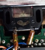
I recently picked up a Midland 13-853 23-channel crystal-controlled CB for a VFO project that I'd like to do. When I first powered it up, I could see that the transmit side was fine - 4W solid and good modulation. However, on the receive side, I've got problems...I found that I had to jiggle the PA/Ext. CB/Off switch to get any RX audio, and the audio that I got was super quiet. It didn't matter if I used an external speaker or not - the audio was still quiet even with the volume up all the way. It was also very distorted. The PA system works and gives off clear, loud, and crisp audio, so no issues there. Board also looks fine and I don't see any cracks either.

I'm wondering if I need to recap the radio since, well, it's close to 50 years old (1976 dated). I assume that it was in storage for a while since there was spider egg shells and dust. I haven't tried using contact cleaner first since I wanted to see if there was anything else I was missing and needed to check before doing so.

Let me know what you all think and what I should troubleshoot next! Thanks!

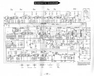
Oh, and I've also included the schematic too...
 

Attachments

  • Midland-13-853-schematic.jpg
    Midland-13-853-schematic.jpg
    177 KB · Views: 6

KANE4109

Member
Joined
Oct 1, 2013
Messages
125
Location
Deer Park, TX
Just one opinion here... but it starts with a question and that is.... what test equipment do you have available?

Here is where my thinking starts....
You checked a couple of boxes of things I was thinking of.

If you have clean, clear, loud PA then the AUDIO circuits and the speaker are fine..... or at least good enough at this point. Good modulation on transmit would tend to back this up and, further would tend to indicate that both secondaries of the audio transformer are good. Also tends to indicate that the mic input and amps are good.

As for the low receive.... I've got to ask.... what is the needle (S Meter) doing? Also, how are you judging that it's audio is weak? Do you KNOW that there are transmissions that you SHOULD be hearing? Sometimes... there is just nothing on there. But assuming that there is RF coming in... or... that you should be hearing more static than you are...... again, what is that needle doing? Is it hugging the bottom? Or is it up and bouncing (even just a LITTLE bounce)? If you have needle activity.....but no static or sound... keep going. If you don't.... do you happen to have another radio that you could use to key up and provide some signal for the Midland?

Here is where the test equipment question comes in....

What I would do first is essentially to attempt a "receive alignment". Hook up an RF generator on a channel with 1 Khz 30% modulation (since it is a 23 channel, channel 13 is sort of "in the middle"). Then try tuning any tuned circuits in the path from the RF amp, through the IFs. If it is an alignment issue... this should bring it up in volume. Just tune each transformer/coil in that path for the peak and see if that doesn't wind up bringing it up to a good level.

However... if it doesn't...... it will be time to use a scope or an RF probe/signal tracer to find out where things are going wrong. I am not saying that capacitors ARE the problem.... but they MAY BE and this would be the point where reasonable people might think that a recap is a good idea. Alignment didn't do it..... so something ELSE is wrong.... and it could well be caps. One plan might be to scour that schematic for all the electrolytic caps in the RF amp/IF strip and demod circuit and replace those first!!!!

The handiest way of all... is if you have a signal generator and can inject modulated RF into the radio so that you have something to work with. Ifyou can "pipe in" S9 signal level and you get nothing out.... THEN you have something TO troubleshoot.

Let me know what you think!

Bob
 

KE0SBX

Member
Joined
Dec 1, 2023
Messages
15
Just one opinion here... but it starts with a question and that is.... what test equipment do you have available?

Here is where my thinking starts....
You checked a couple of boxes of things I was thinking of.

If you have clean, clear, loud PA then the AUDIO circuits and the speaker are fine..... or at least good enough at this point. Good modulation on transmit would tend to back this up and, further would tend to indicate that both secondaries of the audio transformer are good. Also tends to indicate that the mic input and amps are good.

As for the low receive.... I've got to ask.... what is the needle (S Meter) doing? Also, how are you judging that it's audio is weak? Do you KNOW that there are transmissions that you SHOULD be hearing? Sometimes... there is just nothing on there. But assuming that there is RF coming in... or... that you should be hearing more static than you are...... again, what is that needle doing? Is it hugging the bottom? Or is it up and bouncing (even just a LITTLE bounce)? If you have needle activity.....but no static or sound... keep going. If you don't.... do you happen to have another radio that you could use to key up and provide some signal for the Midland?

Here is where the test equipment question comes in....

What I would do first is essentially to attempt a "receive alignment". Hook up an RF generator on a channel with 1 Khz 30% modulation (since it is a 23 channel, channel 13 is sort of "in the middle"). Then try tuning any tuned circuits in the path from the RF amp, through the IFs. If it is an alignment issue... this should bring it up in volume. Just tune each transformer/coil in that path for the peak and see if that doesn't wind up bringing it up to a good level.

However... if it doesn't...... it will be time to use a scope or an RF probe/signal tracer to find out where things are going wrong. I am not saying that capacitors ARE the problem.... but they MAY BE and this would be the point where reasonable people might think that a recap is a good idea. Alignment didn't do it..... so something ELSE is wrong.... and it could well be caps. One plan might be to scour that schematic for all the electrolytic caps in the RF amp/IF strip and demod circuit and replace those first!!!!

The handiest way of all... is if you have a signal generator and can inject modulated RF into the radio so that you have something to work with. Ifyou can "pipe in" S9 signal level and you get nothing out.... THEN you have something TO troubleshoot.

Let me know what you think!

Bob
Wow thank you so much for that info!

As for receiving a signal I can hear very faint static from the speaker. I unfortunately don't have an RF probe handy but I do have a multimeter and I have several other CBs I could use to inject a signal nearby.

As for the needle well...the meter appears to be busted. The needle is stuck on S1 and does not appear to budge, even on transmit too.
 

KANE4109

Member
Joined
Oct 1, 2013
Messages
125
Location
Deer Park, TX
Do you have any electronic parts available at all? One can literally build an RF probe on a popsicle stick that will serve.
Yeah, with no S meter you dont really have a clue how much RF is coming in.

Let me ask you this.... if you have another radio.... could you set it up to pump into either a nearby antenna... or even a dummy load? If dummy load... set the load next to the Midland and key it up and modulate.... see if the Midland "comes alive" a little bit. If it is an alignment issue... having a VERY CLOSE RF source should make it do a little better..... it acts like somewhat of a "sensitivity" issue.... a badly tuned receiver may receive well when the signal is nearby but not do so well when it is farther away.

Since you have no S meter... you would just have to listen and see if the audio out of the MIdland jumps up much.... relying on your ears is kind of "subjective" but if that is what you have....... you run with it! :)
 

KANE4109

Member
Joined
Oct 1, 2013
Messages
125
Location
Deer Park, TX
Wow thank you so much for that info!

As for receiving a signal I can hear very faint static from the speaker. I unfortunately don't have an RF probe handy but I do have a multimeter and I have several other CBs I could use to inject a signal nearby.

As for the needle well...the meter appears to be busted. The needle is stuck on S1 and does not appear to budge, even on transmit too.
At this point, an even more important question is, do you have any alignment tools? The plastic kind like a hex key?

It might be interesting to feed signal from one of the extra radios and turn some of the adjustments and see if the sound comes up. It would be more accurate with test equipment but, we won't let that stop us!!!! :)
 

KE0SBX

Member
Joined
Dec 1, 2023
Messages
15
At this point, an even more important question is, do you have any alignment tools? The plastic kind like a hex key?

It might be interesting to feed signal from one of the extra radios and turn some of the adjustments and see if the sound comes up. It would be more accurate with test equipment but, we won't let that stop us!!!! :)
I do have those tools thank goodness! I had an MFJ Cub that didn't work the first time and wouldn't you know...I had to use my ears too to adjust the receiver :LOL: and as for the electronic components...I have so many of them I have some in my basement, some in my bedroom...I got 'em all over! But you're right - an RF probe would be simple to build.

Thank you so much for the insight and help so far!
 

KANE4109

Member
Joined
Oct 1, 2013
Messages
125
Location
Deer Park, TX
I do have those tools thank goodness! I had an MFJ Cub that didn't work the first time and wouldn't you know...I had to use my ears too to adjust the receiver :LOL: and as for the electronic components...I have so many of them I have some in my basement, some in my bedroom...I got 'em all over! But you're right - an RF probe would be simple to build.

Thank you so much for the insight and help so far!
Absolutely! Is that your callsign by the way? (AI5RR here on this end)
 

KANE4109

Member
Joined
Oct 1, 2013
Messages
125
Location
Deer Park, TX
Sure is, KE0SBX!
To let you know what kind of "nut" you are dealing with.........

BNbS59o.jpg


XG53rhr.jpg
 

KE0SBX

Member
Joined
Dec 1, 2023
Messages
15
You won't believe it but...it DOES work! I do need to shoot some contact cleaner on the switches and pots (ie, Deoxit, WD-40 contact cleaner, etc.) but other than that, this radio works! It's a true gem and I already love it!

All I did was test it two ways - first I TXed from another radio (cheap Maxon CB connected to dummy load) to test the Midland's RX stages. Then, I TXed from the Midland fed into the dummy load to check it's TX stage. The problem...I didn't use an antenna on the Midland for RX so I really couldn't hear what was "on the air." No wonder the RX was so quiet!

Thank you very much @KANE4109, I will more than likely come back to this post for some more troubleshooting tips in the future.

One other question I have about this rig - there is a "blank" space between Channels 22 and 23 on the channel switch...not quite sure what this is. Is it some sort of "hidden channel" setting? I tried to key up on this setting but it didn't put out anything.
 
Last edited:

KANE4109

Member
Joined
Oct 1, 2013
Messages
125
Location
Deer Park, TX
First, WD-40 is not appropriate for switch contacts. If you "have" or "can get" DeOxit that is one of the best. If not, a local auto parts store often has a real spray contact cleaner that is meant for cleaning contacts. These real "contact cleaners" are made to "do their job and then evaporate away". WD-40 has a habit of "sticking around and attracting dirt and grit" which you don't want.

Second, on the subject of "the gap" in the channel selector.... every 23 channel that I ever had or saw had this gap. If you "Google up" the term "CB radio frequencies" and look carefully at the chart there was a gap in every FOUR frequency steps.

Like this:
Channel 1 = 26.965 MHz
Channel 2 = 26.975 MHz
Channel 3 = 26.985 MHz
Channel 4 = 27.005 MHz

Notice that they "skipped" 29.965 Mhz!

Now, look up here at the top of the OLD band.
Channel 20 = 27.205 MHz
Channel 21 = 27.215 MHz
Channel 22 = 27.225 MHz
Channel 23 = 27.255 Mhz
(that is not a typo. They skipped TWO channels worth of spacing between 22 & 23!)

For a reason that I don't know... .they didn't show the "single gaps" that existed from Ch 1 to 19. However, where the DOUBLE gap
was, there was a space left on the dial. My guess would be that it had something to do with the necessary "design" of the switch. What I mean is that....they could design a switch that "mechanically" could handle the ONE SKIP OUT OF FOUR.... but then... up there between
22 and 23 they need to skip TWO channels.... so they just decided to put that blank space in to handle the "extra skipped channel". But I don't know for sure... only a guess.

Those "skipped channels" were (I believe) Radio Control (or RC) channels previously allocated to other services. They were RE-ALLOCATED by the FCC so that in 1977 CB service went from 23 to 40 channels. So look what they did NOW ....starting at CHannel 20:
Channel 20 = 27.205 MHz
Channel 21 = 27.215 MHz
Channel 22 = 27.225 MHz
Channel 23 = 27.255 MHz
Channel 24 = 27.235 MHz
Channel 25 = 27.245 MHz
then....
Channel 26 = 27.265 MHz
Channel 27 = 27.275 MHz
and so on......

They went back and filled in the two missing frequencies.... THEN skipped 27.255 since it was channel 23.
From 26 on up the first two digits of the KHz part (.265, .275, .285,.295... on up to .405) all match the channe number
and there ARE NO MORE SKIPS from 26 and above.

Also notice that after 1977 when 40 channels were adopted ... most, not ALL but most, radios were doing it digitally (because of the adoption of PLL ... or Phase Locked Loop chips... and they use a digital scheme to set the frequency. So there was no more "dial" that had to worry about the skip as far a "display" goes. Just a pair of numeric LED displays that showed the channel number.

But.... "fact from the old times" ... if you go back and look at any 23 channel with a dial... they all either had a BLANK SPACE..... OR.....
some used that as a PA switch position. THOSE radios have no "PA switch on the front panel". You just rotate the dial to the spot between
22 and 23 and BOOM... you are "in PA".

Last, and most of all, I am very glad this has worked out the way it did. Switch contacts DO oxidize after years of sitting and doing nothing and sometimes need a good cleaning (or at least.... someone to come a long and rattle the crap out of them!!!!) before they will work.

And also the importance of that antenna can not be understated. What is happening there is.... a communications radio like that is designed in such a way that it's ability to both RCV and XMT "depends" on having a properly tuned "load" connected to the antenna jack. If no antenna is present..... the receiver is extremely INSENSITIVE and the incoming signal has to really be strong..... like..... IN THE ROOM with you!!!! THAT most likely led to your discovery that when you keyed a local "spare radio" it showed a little life. But yes, the antenna is needed for both RCV and XMT to work well.

Again, I'm glad that has worked out for you and now you can just dive into enjoying that radio for what it is!!!! Have fun... and stay with the hobby! Lots of rewards in it!!!!!!

73, Bob.

(for reference, here is a chart of the official CB frequencies: CB Radio Frequencies and Channels.)
 

slowmover

Temporarily Banned
Timeout for bad behavior
Joined
Aug 4, 2020
Messages
2,544
Location
Fort Worth
First, WD-40 is not appropriate for switch contacts. If you "have" or "can get" DeOxit that is one of the best. If not, a local auto parts store often has a real spray contact cleaner that is meant for cleaning contacts. These real "contact cleaners" are made to "do their job and then evaporate away". WD-40 has a habit of "sticking around and attracting dirt and grit" which you don't want.

Second, on the subject of "the gap" in the channel selector.... every 23 channel that I ever had or saw had this gap. If you "Google up" the term "CB radio frequencies" and look carefully at the chart there was a gap in every FOUR frequency steps.

Like this:
Channel 1 = 26.965 MHz
Channel 2 = 26.975 MHz
Channel 3 = 26.985 MHz
Channel 4 = 27.005 MHz

Notice that they "skipped" 29.965 Mhz!

Now, look up here at the top of the OLD band.
Channel 20 = 27.205 MHz
Channel 21 = 27.215 MHz
Channel 22 = 27.225 MHz
Channel 23 = 27.255 Mhz
(that is not a typo. They skipped TWO channels worth of spacing between 22 & 23!)

For a reason that I don't know... .they didn't show the "single gaps" that existed from Ch 1 to 19. However, where the DOUBLE gap
was, there was a space left on the dial. My guess would be that it had something to do with the necessary "design" of the switch. What I mean is that....they could design a switch that "mechanically" could handle the ONE SKIP OUT OF FOUR.... but then... up there between
22 and 23 they need to skip TWO channels.... so they just decided to put that blank space in to handle the "extra skipped channel". But I don't know for sure... only a guess.

Those "skipped channels" were (I believe) Radio Control (or RC) channels previously allocated to other services. They were RE-ALLOCATED by the FCC so that in 1977 CB service went from 23 to 40 channels. So look what they did NOW ....starting at CHannel 20:
Channel 20 = 27.205 MHz
Channel 21 = 27.215 MHz
Channel 22 = 27.225 MHz
Channel 23 = 27.255 MHz
Channel 24 = 27.235 MHz
Channel 25 = 27.245 MHz
then....
Channel 26 = 27.265 MHz
Channel 27 = 27.275 MHz
and so on......

They went back and filled in the two missing frequencies.... THEN skipped 27.255 since it was channel 23.
From 26 on up the first two digits of the KHz part (.265, .275, .285,.295... on up to .405) all match the channe number
and there ARE NO MORE SKIPS from 26 and above.

Also notice that after 1977 when 40 channels were adopted ... most, not ALL but most, radios were doing it digitally (because of the adoption of PLL ... or Phase Locked Loop chips... and they use a digital scheme to set the frequency. So there was no more "dial" that had to worry about the skip as far a "display" goes. Just a pair of numeric LED displays that showed the channel number.

But.... "fact from the old times" ... if you go back and look at any 23 channel with a dial... they all either had a BLANK SPACE..... OR.....
some used that as a PA switch position. THOSE radios have no "PA switch on the front panel". You just rotate the dial to the spot between
22 and 23 and BOOM... you are "in PA".

Last, and most of all, I am very glad this has worked out the way it did. Switch contacts DO oxidize after years of sitting and doing nothing and sometimes need a good cleaning (or at least.... someone to come a long and rattle the crap out of them!!!!) before they will work.

And also the importance of that antenna can not be understated. What is happening there is.... a communications radio like that is designed in such a way that it's ability to both RCV and XMT "depends" on having a properly tuned "load" connected to the antenna jack. If no antenna is present..... the receiver is extremely INSENSITIVE and the incoming signal has to really be strong..... like..... IN THE ROOM with you!!!! THAT most likely led to your discovery that when you keyed a local "spare radio" it showed a little life. But yes, the antenna is needed for both RCV and XMT to work well.

Again, I'm glad that has worked out for you and now you can just dive into enjoying that radio for what it is!!!! Have fun... and stay with the hobby! Lots of rewards in it!!!!!!

73, Bob.

(for reference, here is a chart of the official CB frequencies: CB Radio Frequencies and Channels.)

Great post. Thx!

.
 

KE0SBX

Member
Joined
Dec 1, 2023
Messages
15
Now...I've gotta see if I can get the S-meter working again. Word of advice, it's a pain in the rear to get out and put back in! It also is encased in plastic completely so I can't access the needle screws period.

Any thoughts or ideas on this?

Thank you!
 

KANE4109

Member
Joined
Oct 1, 2013
Messages
125
Location
Deer Park, TX
Now...I've gotta see if I can get the S-meter working again. Word of advice, it's a pain in the rear to get out and put back in! It also is encased in plastic completely so I can't access the needle screws period.

Any thoughts or ideas on this?

Thank you!
I'm no expert at these.... not even a novice. But I assume that it had to be "put together". Does it look like it was glued or something? I would think that there would be some kind of capability to snap it open...... but I don't know.....
 

KE0SBX

Member
Joined
Dec 1, 2023
Messages
15
Here's a photo of the top of the S-meter, should've taken photos when it was out, but the bottom looks the exact same as the top. It might be able to be snapped open but...I really don't wanna try that if I don't have to.
 

Attachments

  • 20240907_122231.jpg
    20240907_122231.jpg
    71.9 KB · Views: 4
Top