• To anyone looking to acquire commercial radio programming software:

    Please do not make requests for copies of radio programming software which is sold (or was sold) by the manufacturer for any monetary value. All requests will be deleted and a forum infraction issued. Making a request such as this is attempting to engage in software piracy and this forum cannot be involved or associated with this activity. The same goes for any private transaction via Private Message. Even if you attempt to engage in this activity in PM's we will still enforce the forum rules. Your PM's are not private and the administration has the right to read them if there's a hint to criminal activity.

    If you are having trouble legally obtaining software please state so. We do not want any hurt feelings when your vague post is mistaken for a free request. It is YOUR responsibility to properly word your request.

    To obtain Motorola software see the Sticky in the Motorola forum.

    The various other vendors often permit their dealers to sell the software online (i.e., Kenwood). Please use Google or some other search engine to find a dealer that sells the software. Typically each series or individual radio requires its own software package. Often the Kenwood software is less than $100 so don't be a cheapskate; just purchase it.

    For M/A Com/Harris/GE, etc: there are two software packages that program all current and past radios. One package is for conventional programming and the other for trunked programming. The trunked package is in upwards of $2,500. The conventional package is more reasonable though is still several hundred dollars. The benefit is you do not need multiple versions for each radio (unlike Motorola).

    This is a large and very visible forum. We cannot jeopardize the ability to provide the RadioReference services by allowing this activity to occur. Please respect this.

Transmit to Transmit Antenna Isolation?

Status
Not open for further replies.

pboyd

Member
Joined
Jun 5, 2015
Messages
38
I'm reworking a multi-repeater system to have a common receive antenna -> pre-amp -> multicoupler -> [repeater 1, repeater 2]. But I don't have the budget for a transmit combiner. So that leaves me with 2 separate transmit antennas. I've always been told you want about 10' vertical antenna separation for different UHF repeaters (so about 50dB+ isolation) but my understanding is that was mostly for the TX from one repeater to the RX on the other repeater. I can't seem to find anything about TX to TX isolation.

So how much isolation/separation do I need between two TX repeater antennas?
 

chief21

Member
Premium Subscriber
Joined
Mar 2, 2004
Messages
1,855
Location
Summer - Western NC; Winter - Tampa Bay FL
So how much isolation/separation do I need between two TX repeater antennas?

I can't give you an answer in engineering terms, but in a practical sense I would say about 10-15' between the top of one antenna and the bottom of the one above. This is based on conditions at a Motorola-engineered, ten-channel UHF tower site with ten TX antennas and one top-mounted RX antenna.
(But if I were you, I'd get that verified by an engineer before placing the antennas.)
 

prcguy

Member
Premium Subscriber
Joined
Jun 30, 2006
Messages
15,943
Location
So Cal - Richardson, TX - Tewksbury, MA
Its not the antennas you want to isolate so much, its the transmitters. If the transmit antennas are far enough apart as to not cause undesirable radiation pattern changes its usually easier and much more effective to use isolators and cavity filters at the transmitters to achieve isolation. If you are at a commercial site they most certainly require an isolator on every transmitter anyway.

A single isolator gives about 35dB isolation to outside signals within the same band. If the nearby transmitters are a couple of MHz away a single cavity filter can add 10 to 50dB or more isolation depending on the frequency separation. You can't get anywhere near that much isolation with antenna separation unless you can move them very far apart vertically.

The whole purpose for this is to avoid having an outside signal mix with your transmitter creating Intermodulation Distortion.

For your master receive antenna the preselector comes first, then the preamp then the dividers. You need some vertical separation of the receive antenna over all transmit antennas and the TX/RX antenna separation in dB plus skirts of the receive preselector combined with transmit cavity filters should give you a big number in isolation, like 80dB and preferably much more. With a master receive distribution every transmitter in the system will need a band pass cavity filter to keep broad band transmitter noise out of the receive band.
 

pboyd

Member
Joined
Jun 5, 2015
Messages
38
This isn't a commercial site. These repeaters are at an event site on a temporary mast for a week out of the year.

In the past I've been separating the duplexed TX/RX antennas by 10' so about 50dB's of isolation. Is that sufficient for my use case or do I need to add filters for more isolation?
 

prcguy

Member
Premium Subscriber
Joined
Jun 30, 2006
Messages
15,943
Location
So Cal - Richardson, TX - Tewksbury, MA
I don't believe you can achieve 50dB isolation on the same mast or tower at any vertical separation. Certainly not at 10 or 20ft. 50dB is a 100,000:1 ratio or change. However with 10ft of vertical separation and band pass cavaties on all receivers and transmitters you can get 100dB or more TX/RX isolation. Its all in the filter skirts. It also depends on the receiver, a broad band no tune receiver will need much more filtering and a tuned to frequency front end receiver will get by with less.

Many years ago I tried about 10ft of vertical separation and a single 1/4 wave cavity on the transmitter and receiver of a GE Master II repeater, which has a very high performance tuned front end receiver. This was on 2m amateur with about a 1MHz split and I could not get it to work. I eventually got a PD 6 cavity bpbr duplexer and it worked great.

This isn't a commercial site. These repeaters are at an event site on a temporary mast for a week out of the year.

In the past I've been separating the duplexed TX/RX antennas by 10' so about 50dB's of isolation. Is that sufficient for my use case or do I need to add filters for more isolation?
 

prcguy

Member
Premium Subscriber
Joined
Jun 30, 2006
Messages
15,943
Location
So Cal - Richardson, TX - Tewksbury, MA
No, I don't believe you will get 50dB of isolation with only 12ft of spacing at UHF. Its entirely dependent on the antenna, feedline decoupling, etc. You might say you can achieve up to 50dB in a perfect scenario with the wind behind you, God willin and the creek don't rise but don't count on it.

Does the XPR8400 have a couple of mobile radios inside a box like an 8300? Do you have hardware to align when changing frequencies or do you just program and go? If its program and go it has a broad band receiver and relies on external filtering to duplex. And you need a filter on the transmitter, otherwise how do you keep the broad band transmitter noise out of the receiver?

To test all this you need a local speaker on the repeater. Disable the transmitter or stick a load on it. Have a distant radio that does not produce full quieting transmit and note the quality of reception. Enable the transmitter. Without filtering that noisy signal will get noisier or will go away. When there is zero difference in reception quality at the repeater receiver with the transmitter on or off, then you are on track. If you don't perform a test like this then you have no idea how well or how bad your repeater system is working.

So these old charts are over estimating the isolation you get? Isolation between the repeater receiver and RF sources

I'm on the 70cm band in the business frequencies running 2 XPR8400 repeaters in digital mode. Not sure how great the front end receivers are in those but they seem pretty solid.
 
Last edited:

pboyd

Member
Joined
Jun 5, 2015
Messages
38
Haven't seen inside the XPR8300 so I can't compare but it does look like there are just two radios in the box with some other controller hardware. And yes it's just program and go.

Background: I was previously using cheap chinese mobile style duplexers for the repeaters. I had 0 issues with the primary repeater which was at the top of the mast. Repeater 2 which was about 10' down had some intermittent issues and we had a third repeater even further down that basically didn't work for squat.

I've run some tests with a mobile radio transmitting GPS packets every 5 seconds and program I wrote to grab the RSSI for those packets out of the repeater. For the tests I got good coverage on the Repeater 1 setup, slightly less good for the repeater 2 setup but nothing horrible, and really bad coverage out of repeater 3. Switching things to seperate RX antenna with a multicoupler got me almost back to repeater 1 levels for all 3 repeaters. Adding the pre-amp pushed my RSSI levels up past my original repeater 1 setup for all three configs. So I think I'm on the right path here. Just want to make sure I'm not introducing more problems than I'm solving.

So putting a couple of cavity filters on my TX lines should help make sure I don't have any issues from the transmit antennas being too close to each other?
 

prcguy

Member
Premium Subscriber
Joined
Jun 30, 2006
Messages
15,943
Location
So Cal - Richardson, TX - Tewksbury, MA
What is the frequency spacing between repeaters? You really need an isolator on each repeater transmitter to start with, otherwise when two or more key up at once you will produce a spectrum of junk that will probably take out your reception. If the frequencies are all close together then the filters will not benifit the isolation between transmitters but you really need them to keep broad band transmitter noise out of the receivers.

The transmitter noise might be waaaay down at your 5MHz split but waaaay down can still be a huge signal since the transmit and receive antennas are right on top of each other. You need the filters to cut out all energy that would otherwise cover your receive frequencies.

I've dealt with situations like you are doing for many years. Repeaters that kind of work but not quite and performance varies over time, etc. I'll drop in a temporary repeater properly tuned up with a high isolation duplexer and the difference in coverage can be amazing. Then $$ is spent to do the job right and the repeater owner is happy and never looks back.

Haven't seen inside the XPR8300 so I can't compare but it does look like there are just two radios in the box with some other controller hardware. And yes it's just program and go.

Background: I was previously using cheap chinese mobile style duplexers for the repeaters. I had 0 issues with the primary repeater which was at the top of the mast. Repeater 2 which was about 10' down had some intermittent issues and we had a third repeater even further down that basically didn't work for squat.

I've run some tests with a mobile radio transmitting GPS packets every 5 seconds and program I wrote to grab the RSSI for those packets out of the repeater. For the tests I got good coverage on the Repeater 1 setup, slightly less good for the repeater 2 setup but nothing horrible, and really bad coverage out of repeater 3. Switching things to seperate RX antenna with a multicoupler got me almost back to repeater 1 levels for all 3 repeaters. Adding the pre-amp pushed my RSSI levels up past my original repeater 1 setup for all three configs. So I think I'm on the right path here. Just want to make sure I'm not introducing more problems than I'm solving.

So putting a couple of cavity filters on my TX lines should help make sure I don't have any issues from the transmit antennas being too close to each other?
 

pboyd

Member
Joined
Jun 5, 2015
Messages
38
I'm at 5 MHz spacing on the pairs and the two pairs are 8 MHz from the high on one pair to the low on the other.

Also to be clear the problems follow the antennas/feedline on the tower not the repeaters. The lower antenna/repeater pairs have issues receiving portable radios at a distance. Nothing has any issues hearing the repeaters. I've even cranked the repeater power down a bit in case the receive issues were desense but since switching to heliax cables for the feedline I really haven't had much desense according to the repeater RSSI readings taken through RDAC. (I've also written a program to keep a log of noise floor so if I can see if I've got some issue when I'm not standing there running RDAC, but that will have to wait for next year at the event).
 

freddaniel

Member
Joined
May 6, 2011
Messages
120
Location
Newport Beach, CA
You have several issues to deal with to achieve maximum performance. If properly designed, the receiver multicoupler should help you a lot. However, you will need a pre-selector filter ahead of the preamp and a small attenautor between the preamp and your 4 way splitter. Since you have only told us your 3 repeaters are spread over 8 MHz, then for discussion I will assume the Tx frequencies are maybe 462.2, 463.5 and 464.9, with the receive frequencies at 467.2, 468.5 and 469.9, which places the outside frequencies about 8 MHz apart. With this in mind, your pre-selector needs to be aligned for 467.2 to 469.9 and any excess bandwidth needs to be above 469.9 to maximize the attenuation on the transmit frequencies. The preselector can be a simple & compact 4 to 6 resonator filter like the old Celwave HFE8459A usually found on Ebay for around $130, and the bandwidth is typically 3 MHz with 2 dB loss. Attenuation on the nearest Tx frequency is about 25 dB and greater on the others. Many older two-way shops have these in-stock.

The output attenuator is required to reduce the excess gain of the preamp. If you were to buy the Mini-Circuits ZX60-P103LN+ for $65, the gain is about 18 dB. The 4-way splitter like the Mini-Circuits ZB4PD-462W-N+ for $110 with N connectors has 7 dB loss. Cables add maybe another 3 dB loss, so the preamp will be running 8 dB hot, which will reduce the dynamic range of the repeater receivers and raise the potential of interference by at least 8 dB. Therefore you need to install an 8 db attenuator BETWEEN the preamp and splitter. Terminate the spare splitter port with a small 50 ohm load and wait to install your 4th repeater. That should make all the receivers great.

The proper way to combine the transmitters is to use a dual-junction Isolator on each transmitter and combine with two 3 dB Hybrid couplers. These will allow you to operate the repeaters on any frequencies, including adjacent channels without interference. You will lose about 7 dB per channel if you had 4 repeaters, but with three channels, one channel would be 3.5 dB down. Your repeaters are likely running far more power out than is necessary so the loss of power is of no consequence. Each hybrid will require a load adequate to handle 50% of the power out from the two repeaters to each. If the repeaters are set to 50 watts each, the you will need [25+25] a 50 watt load that will get really warm.

The hybrids are listed on Ebay as “hybrid couplers” and the perfect model is the Sage 751, Microlabs CA-25N or several Narda models. Some 3 dB hybrids like the Microlabs CA-15N designed for 200-400 MHz can work out of range with a small power imbalance between ports. Watch Ebay as these do come available in the $25 to $100 range.

The dual-junction isolators can be hard to find, but you can use two singles in series. I will be listing on Ebay about 80 used single junction MA-COM circulators for 430-470 MHz soon, so I know these are available. Typically on Ebay, singles go for $75 -$125 and dual-junction go for $125-$175.

You will require a low pass filter between the Hybrids and your SINGLE TRANSMIT ANTENNA. I hope this helps. If you need more info or diagrams, just ask.
 
Joined
Apr 30, 2008
Messages
1,373
Location
Pittsboro IN
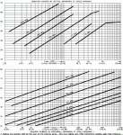
I've had these charts for years, don't know who did them.
@ Fred - do you still have an RF website? I thought I had it bookmarked but can't find it now.
 

Attachments

  • antenna spacing.gif
    antenna spacing.gif
    102.3 KB · Views: 18
  • antenna isolation.pdf
    880.6 KB · Views: 11

freddaniel

Member
Joined
May 6, 2011
Messages
120
Location
Newport Beach, CA
I have found those charts to be reasonably accurate, after you take into account several unspoken conditions. I am sure you know this, but for the benefit of the many readers still learning, I offer the following:
1. The stated isolation is only achievable if you do not have any reflective surface within the near-field [50-150 ft depending band] to create an alternate path for the signal.
2. Most antennas are not single dipoles, so measure from the two closest radiating portions of the antennas.
3. Don't forget about the coax of the upper antenna passing behind the lower antenna, that might allow coupling. Use Heliax or RG-214.
4. Some gain antennas tend to provide a little more isolation due to the signal compression at the horizon.
5. Don't forget the jumper cable between antenna and Heliax. Use RG-214 cable with silver-plated connectors to prevent radiation. Do not connect Heliax or Superflex directly to the antenna as it can short if the cable is moved by another climber.

The easiest way to determine isolation is to simply measure it. The Anritsu MT8212B with Opt. 21 will measure isolation directly. These used instruments have been selling weekly on Ebay for about a year for around $450 to $650. It has an antenna analyzer, a spectrum analyzer with a tracking generator, and other neat stuff. Watch new listings, a new one is started at $50 every 10 days. I have purchased several as gifts.

My info website is www.OpenLMR.org and it is incomplete, due to a lack of time. I also seek authors and material.
 
Joined
Apr 30, 2008
Messages
1,373
Location
Pittsboro IN
The Anritsu MT8212B with Opt. 21 will measure isolation directly.

Would a 2 port VNA do this? It's more expensive but I have 2 single port VNAs that Copper mountain's software emulates to a dual port.

I have seen near field defined as 2 to 4 wavelengths in various documents, what number do you prefer?
Thanks for the link and nice to see you back here, it's been a while since you posted.
 

freddaniel

Member
Joined
May 6, 2011
Messages
120
Location
Newport Beach, CA
YES, a two port VNA would also provide the isolation, or a scalar network analyzer, or a simple signal generator and spectrum analyzer, or a receiver. My point was to share with our readers a valuable portable test instrument was now widely available used at a reasonable cost. Few radio enthusiasts have VNAs or know the difference between that and lower-cost alternatives.

You are probably right about 2 to 4 wavelengths, but VHF is 30 to 300 MHz and UHF is 300 to 1000 MHz, both of which are common land-mobile bands. At 30 MHz a wavelength is 10 meters or 33 feet. Thus 4 times 33 equals 132 feet. So my 150 ft is off by 12%. Not bad for a quick guess. Again, the point was to illustrate that if you have a structure with a transmit antenna at 40 ft and a receive antenna at 60 ft, then you might expect 40 to 50 dB isolation. However, if a metal building or tower was within 100 ft or less, it could reduce your isolation due to signal reflection off of the secondary structure. Obviously, the type of antennas and their directivity will factor into the situation. Not every problem has a simple answer. Learn to adapt.
Today, for example, I tested an 85 ft length of 7/8 Heliax on a tower with my Anritsu Sitemaster at 900 MHz., it appeared open, regardless of whether we terminate it with 50 ohms, shorted it, or left it open. When terminated with 50 ohms, it measured 50 ohms with a VOM, so I knew we had continuity. I later thought to sweep it over a broader range and found it had a return loss of 15 dB at 6 MHz and got worse as the frequency increased. We switched to a spare cable and plan on replacing the bad Heliax, which is likely full of water, or ??
 
Joined
Apr 30, 2008
Messages
1,373
Location
Pittsboro IN
My point was to share with our readers a valuable portable test instrument was now widely available used at a reasonable cost.
Well, my point was if you said no I could convince my wife I needed a new toy. And here I was thinking you were a friend....

I later thought to sweep it over a broader range and found it had a return loss of 15 dB at 6 MHz

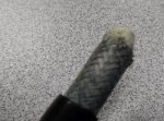
I swept a unlabeled coax and got 8dB return loss, got the roof and found a male N facing skyward, the GPS antenna had been removed and the connector had filled with water. You can see green tint on the dielectric.
 

Attachments

  • SAM_0385.jpg
    SAM_0385.jpg
    68.6 KB · Views: 7

TampaTyron

Beep Boop, Beep Boop
Premium Subscriber
Joined
Feb 1, 2010
Messages
1,131
Location
Phoenix, AZ
When I am troubleshooting customer or dealer MOTOTRBO systems (typically 1 to 2 per week), for antenna isolation I use an Anritsu S412E and generate a DMR test pattern on one cable and receive the same pattern on the other cable. If I generate at 0dBm and measure the pattern on the other cable at x dBm, then I subtract the cable loss on each cable path. TT

[/QUOTE]
Today, for example, I tested an 85 ft length of 7/8 Heliax on a tower with my Anritsu Sitemaster at 900 MHz., it appeared open, regardless of whether we terminate it with 50 ohms, shorted it, or left it open. When terminated with 50 ohms, it measured 50 ohms with a VOM, so I knew we had continuity. I later thought to sweep it over a broader range and found it had a return loss of 15 dB at 6 MHz and got worse as the frequency increased. We switched to a spare cable and plan on replacing the bad Heliax, which is likely full of water, or ??
[/QUOTE]
 

TampaTyron

Beep Boop, Beep Boop
Premium Subscriber
Joined
Feb 1, 2010
Messages
1,131
Location
Phoenix, AZ
I do 3 measurements:
-from the perspective of the multicoupler, do I see any same site tx at stronger than -55 on spec an?
-dmr pattern ant to ant isolation stronger than -65?
-desense test of 5% BER through iso-tee on repeater RX with termination on RX, then connected to RX with all repeaters TXing..... is the difference between no site tx and all site tx more than a few dB?

TT
 
Status
Not open for further replies.
Top