Trying to find out how to properly measure antenna SWR and Watt readings

Status
Not open for further replies.

paulears

Member
Joined
Oct 14, 2015
Messages
905
Location
Lowestoft - UK
I did some research into all kinds of portable antennas and put the results in a video.
Devising a way to even test the stupid things was really awkward to get meaningful results and the majority will perform very differently on different sized and constructed radios, with people with big hands, small hands or sitting on a work surface. Left me convinced most antennas supplied as after market 'better' ones might well be worse than the one that came with the radios.
 

W5lz

Active Member
Joined
Feb 28, 2019
Messages
617
I guess there are other tests but this is as good a testing as I've seen. It does mention the fact that the size of the hand holding the thing makes a difference, and other aspects that aren't commonly accounted for. How well any/all antennas work are specific to the radio they are use on (and how), also something that isn't mentioned often (if ever).
In specific instances an after-market antenna may be superior to the one supplied. But, no matter who makes that after-market antenna it's going to be a gamble. Don't count on it.
Since any/all HT antennas are going to be 'shortened' from a standard 1/4 wave it will not have the performance of that 'standard' 1/4 wave. So, it proves the point that an HT is for short ranges, or for convenience only. If you expect an HT to perform as well as a 'real live' antenna you are in for a big disappointment. If what you want to be able to hear is at a short distance then an HT -might- be a good choice for a 'first radio'. In general, they are terrible for talking at anything but a short distance, a much shorter distance than the thing is capable of 'hearing'. Personally, I think that's a huge 'turn-off' and probably the reason why there are some who get a license and never use it for very long.
One of the sort of standard jokes about HTs is that the best way of using one is by climbing on top of your house and holding it as high as possible...
 

LostSignal

Member
Joined
Aug 7, 2013
Messages
62
Location
SoCal
Just WOW!!! My word searching is REALLY BAD???!!! Just out of curiosity, PLEASE tell me what you typed???

I was typing, "how do they make a 2m antenna so short" and all different other ways of wording that... like aLOT of different ways and I kept getting the same similar "hits/results".

^^^THAT... what you posted^^^ is what I was looking for!!! Thank you for that.

Trying to play with a portable antenna for getting it on the frequency you want can be trying. The best and simple way is to get the info on the antenna you have and look for the cutting chart the company that supplied it.

Normally there is a helical coiled length above the base that looks like a very small door spring to close a door that is incased in the rubber type coating. The cutting chart will indicate how long the long top section of the whip should be for the frequency range your trying to use.

You could consider a mobile radio and a mag mount to put on the roof. It isn't that hard to install one. If your into learning about radios, you might consider an old radio like a Motorola Spectra. They come in different bands line low band, VHF and UHF. It is not that hard to put them on the ham frequencies. Plus there is plenty of info on the Internet about them. The down side is you need a computer with a clock speed around 1GHz or lower to be able to run DOS operating system on it. Then it will take a RIB (Radio Interface Box) to go from the serial port on the computer to the RIB.

You can make your own cables to go from the computer and the RIB. Then make your own cable to go from the RIB to the radio. This same cable will fit all the Spectra mobiles except the front dash mount radio. This takes a different cable from the RIB to the radio.

The web site called Batlabs contains all the cabling information you will need.

If your more comfortable with a commercial radio, then go out and buy one. There are a good number of them on the market that are sold by many companies.

You can use a mobile in your home, but it will take an AC power supply to provide the need current to match what the transmitter requires with a little to spare. A simple dipole antenna will get you started.

There are some very knowledgeable people on the board here. So if you have Questions, just ask away and someone will come back and provide some help.

You might get on the Internet and do a search to see if there is a ham club near you. Go to some of the meetings and get to know the people there. You might even find someone to take you under their wing and be a mentor for you.

Jim
Believe it or not, I used to do SOME programming Moto radios and even started programming Harris radios, which, sorry, I do NOT care for Harris radios... well, the radios are actually pretty damn nice, but MAN, pinout, their radio name/models can be a bit confusing at times, etc.

Anyways, I mainly dealt with CDM 750, 1250, etc. I used to work along side first responders and alerting systems. BUT, with all that, I've never had to "build" antennas and such. That is a SUPER LONG STORY in itself, but just know that. I had to build custom pinout cables for XTL's, CDM, Spectra, and the list goes on. I know about Call Alert, DTMF, Two-Tone Sequential, Tone Remote (although it is getting a bit fuzzy now remembering how the low guard tone and high guard tone work... but anyways, building an antenna is very new to me and seems interesting. I have a tech class license, but haven't really been on air for quite some time... family as well as other things that were going on the past few years.

Thank you for that information either way!!!

Anyways, trying to pick up where I left off going on about 3yrs now.

Literally, right now, just today, I bought some parts to start making my own 2m vertical. Simple, I know, but I'm trying to learn and I even have an idea that I THINK might work, but I'll wait to build it, test it, and then hopefully take pictures and post it. I've NEVER heard it being done for a 2m vertical or, at the very least, have seen anyone mentioning/posting the idea I have in mind... anyways, I want to do it first and then show you guys...

Anyways, thank you SO MUCH people. I'm doing my best the fastest that I can and trying to learn on my own as much as possible. I just may need help here and there, but I do NOT mind reading on my own and doing my own research. As you can see, my "research wording is just bad"... HAHAHAHAHAHAHA, what can I say???

Btw, I STILL have an XT that I built quite a few years back running DOS v3.30 with a 25MB Seagate on a RLL/MFM controller.
 

paulears

Member
Joined
Oct 14, 2015
Messages
905
Location
Lowestoft - UK
After many, many years in radio, I now do have a little smirk, privately when somebody buy a cheap hand held radio and then tries to make to go further. If you look at the Harris (and others) military kit - the only way to get further is to get the antenna up higher and in the clear on those long and quite ridiculous antenna extenders that get the important bit up over your head, in the clear.

At a radio rally once I saw a guy with a plastic, copper foil lined hard-hat, with a ¼ wave poking out the very top. Looked stupid, but probably the best portable antenna I've ever seen!
 

prcguy

Member
Premium Subscriber
Joined
Jun 30, 2006
Messages
16,693
Location
So Cal - Richardson, TX - Tewksbury, MA
Have you ever actually measured the loss through PL-259s at UHF? The loss is only a couple of tenths of a dB for cheap connectors and less for good ones. Motorola used them on UHF repeaters where there would be at least six silver Teflon PL-259s in both the transmit and receive path of the duplexer and the loss was just fine.

One PL-259 would be on the duplexer input, two more for the jumper to the next cavity and two more on the last jumper from the cavity to the T adapter, then one more for the antenna connection. Depending on the repeater there could be one more on the transmitter. I think only one or two PL-259s in your 70cm hamster setup would be just fine.


As a side note, you may want to look at the use of the -239 connectors on UHF, they really don't do very well in that frequency range.

Also,
If you want to measure JUST the antenna, try and take as many of the cables out of the picture. Since any cable losses will make it look like the SWR is lower than the antennas mismatch. Something to remember is that the SWR reading is power going in direction towards the radio, usually it's from the signal being reflected by the antenna, but if you are near another transmitter, you'll be reading the other transmitted signal.


Also.
Your excitement about the subject is very encouraging. Thank you.

Joel
 

W5lz

Active Member
Joined
Feb 28, 2019
Messages
617
All connectors, no matter what kind, have some amount of loss. Until you get to and above UHF that loss isn't all that unreasonable. Why use a PL-259/239? 'Cuz they are common and easier to put on than some other type connector$. If it ever gets to the point where you are worried about fractions of a dB in loss, you are really 'pushing' the envelope. There are better ways, but are you willing to go to that much trouble??
 

W5lz

Active Member
Joined
Feb 28, 2019
Messages
617
You -should- pay attention to SWR, but, it's certainly not the best indicator of how well an antenna system is working. It's a sort of "ball-park" figure, not an exact one. It's used mainly because it's easy to measure. Actually, it's a terrible way of doing things, but it's the indicator that most people use to see how 'good' something is.
 

W5lz

Active Member
Joined
Feb 28, 2019
Messages
617
Search for the textbooks used for a college electronics course. That's what I got it from, some 50 years ago. You'll run across something called 'hole technology', which was very new at the time. Almost changed my major to knitting, or art appreciation...
 

flametamer

Member
Joined
May 13, 2002
Messages
117
Location
Benton, MS EM42ut
Another quick question I do have though and BELIEVE ME, I TRIED GOOGLIN G using various wording and such...

My question is:
How do they make a 2m antenna only about, say around 6in tall or there abouts??? What is going on underneath that manufactured molding and such???


Is there simply wire wrapping going on underneath at the base of that antenna, for example? This is one of the antennas that I have as well.


Dt
 

LostSignal

Member
Joined
Aug 7, 2013
Messages
62
Location
SoCal
So I have most of everything I need to build my first antenna, a simple 1/4wave 2m vertical using an SO-239 Chassis mount connector.

My only question at the moment is, for the vertical, does the antenna length start at the flange where my ground plane will be?
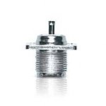
217aB32whZL.jpg

The pic is a stock photo, but what my connector looks like anyways.

The center conductor is where the vertical is going to be soldered to, of course.

Anyways, where does the radiating antenna "start"? It's calling for, "19.21in" for 146MHz, for the center band. Do I just cut, within reason, 19.21in for my metal rod???
 

LostSignal

Member
Joined
Aug 7, 2013
Messages
62
Location
SoCal
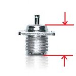
It starts where the coax outer shield ends or where the coax center conductor and outer shield separates.
On the connector in the picture you would measure from the base of the center pin where it comes out of the insulator.

This section measures approx 17.850mm = 0.702in
SO239_ChassisMount_p2.jpg

So, this section SHOULD be included as part of the vertical then, correct?
 
Last edited:

radiohead90

Member
Joined
Nov 21, 2009
Messages
23
Hi all,
Well, to any of the mods and what not, it's been quite some time since I've last logged ON and after reading the "Warning", I REALLY HOPE I am not doing this thread incorrectly or anything as that is not my intentions at ALL!!!

So, to the point as much as I can... I have multiple SWR/Watt meters (i.e. a Diamond SX-200, SX-400, a cheaper Philmore, etc). I know the cables I have are "good" as I get same/similar readings/results. I will continuity check them, but again, I doubt the countless cables I have, PL-259 to PL-259 "store bought" premade type cables are bad.

So, what happens is, I'm trying to simply connect my Boafeng UV-5RA, for example, and the original antenna it came with along with other dual band antennas with one of them being a Diamond SRH701 dual band, making sure to connect the transmitter end to the input side of the SWR meter and the antenna to the output side. Pretty straight forward as it is labeled on the back of the meter. This is done with my PL-259 connectors and just a few adapters to make the connections. I'm using a "pigtail", if you will for my transmitter side so as to not put strain on the sma connector. That pigtail is also "store bought", from HRO... so I highly doubt there is anything wrong with that connector as well.

What I seem to find is that, after calibrating for SWR measurement reading, for VHF, I transmit on L or H and sometimes my SWR will be within around a 2 or below or sometimes +5 to 1 or some ugly SWR reading? Then, as I moved my Boafeng HT closer to the meter, it seemed to DROP in SWR???

My question is this, does cable length and being a certain distance away have to be done in order to get the correct SWR reading? How do I know what the correct reading really is? I really don't know how else to ask the question on this and hope someone can somewhat understand what I am trying to say here?

Finally, I'm doing an "experiment" with 2m and 70cm with antennas and cable lengths, if you will, and this happen to come up along with questioning what is right and wrong when taking SWR measurement readings.

And actually, my actual final question for now is, does the cable actually become part of the antenna system? Meaning, once I get SWR readings with a certain cable length, does that cable length HAVE TO BE part of the end result with the final build of the antenna cable system? If I get an acceptable SWR reading, say with a 2ft cable as strictly as an example, do I have to leave it at 2ft cable length or can I change the cable length to shorter or longer just as long as it is a 50ohm cable???

Boy, I REALLY hope I am making sense with what was just stated above for someone to help me with this and hope it ultimately helps someone with a similar issue and/or question?

-LostSignal
The best why to perform this test would be using a VNA of some sort aka antenna analyzer with a sma adapters on the input connector. Anything else would provide inaccurate readings. As for power ( Watts ) out of the radio itself. Purchase a 50 ohm dummy load and connect it to the output of your watt meter. Connect the other side directly to your port with an adapter if possible. If you use a coaxial cable to connect the portable to the watt meter you will have feed line loss especially on any uhf frequencies. Good Luck
 

LostSignal

Member
Joined
Aug 7, 2013
Messages
62
Location
SoCal
The best why to perform this test would be using a VNA of some sort aka antenna analyzer with a sma adapters on the input connector. Anything else would provide inaccurate readings. As for power ( Watts ) out of the radio itself. Purchase a 50 ohm dummy load and connect it to the output of your watt meter. Connect the other side directly to your port with an adapter if possible. If you use a coaxial cable to connect the portable to the watt meter you will have feed line loss especially on any uhf frequencies. Good Luck
Thank you for that!!!

WOW, you guys are AWESOME!!!

I hope to have my antenna, as simple as it is, built within the next few days. I'm still buying some things here and there, but the rest is ready to be put together. I just literally got back from ACE Hardware.

Anyways, I'll be posting my build as it goes along.
 

LostSignal

Member
Joined
Aug 7, 2013
Messages
62
Location
SoCal
Okay, another question for you guys, how do you calculate how much wattage a homemade vertical can withstand?

I'm using a 1/16" round brass rod for this particular build... I understand it isn't the best for corrosion "resistance".

I'm pretty sure the thing could withstand, at least, 10W probably even 25W? In either case, how does one calculate that?

Finally, I'm figuring that it depends on the material being used as well (i.e. steel will handle more wattage vs brass, for example... I'm assuming here)?

I'm likely going to use my FT-8900R as the test radio?

Thanks guys!!!
 

W5lz

Active Member
Joined
Feb 28, 2019
Messages
617
What determines the amount of power it's possible to feed an antenna is/are the insulators used in making that antenna. The size of conductor, the wire/rod/tube size doesn't make that much difference. What's used as insulators can and certainly do make a difference. Even so, it's all 'relative', you gotta factor all of the abilities of the things use into "will it stand that much?". I've used #18 wire for antennas and it didn't 'melt' with full legal limit. There are huge differences between mechanical abilities and electrical abilities...
 
Status
Not open for further replies.
Top