OK, with a standard USB cable, Green goes to pin 1, White to pin 2, Red to pin 3 and Black to pin 4. Of course, you'll need a PMLN5072A accessory plug kit with pin tips.
FWIW, I double-checked my cable (along with several factory cables) and it matches what I initially posted. No big deal though, as you said you got yours to function properly.I made up a cable according to the instructions given earlier in this thread by KG4INW and it didn't work. Computer didn't recognize the device. So I reversed the data+ and - lines (green and white wires) going to pins 1 and 3 and it worked. So the pinouts for my cable are as follows:
White Data - Pin 1
Green Data + Pin 2
Red Vbus Pin 3
Black ground Pin 4
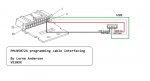
Looking at the back of the radio the connector facing you the pins are as follows:
Upper left side of the connector is pin 2
Lower left side of the connector is pin 1
Pin 4 is next to pin 2
Pin 3 is next to pin 1