michaelscoofield
Member
- Joined
- Apr 12, 2020
- Messages
- 68
- Reaction score
- 10
My Mil air BPF for 230-380MHz 
is in construction now...
is in construction now...

I believe the AM path uses the FM narrow and wide filters, so 6k/12k (at -6 dB). I am not clear whether one can select wide/narrow when in AM mode on this radio.So simply to ask, what filter bandwidth is used on AM in case of IC-208 please?
If it is too narrow, then lack of 8.33k could be an issue for scanning the band.
If it is a bit wider then it would work with let say 10k steps, isn't it?
-m
Ahh, many thanks. I should read manual own self first for next time...I believe the AM path uses the FM narrow and wide filters, so 6k/12k (at -6 dB). I am not clear whether one can select wide/narrow when in AM mode on this radio.
Edit: Having read more of the manual and specs it seems clear that AM and AM-narrow are both available, so 12k for standard AM and 6k for narrow AM (these are at -6 dB on the filter...the -60 dB filter width for each is 30 kHz and 20 kHz respectively.
")
Ahh, many thanks. I should read manual own self first for next time...
So, it seems that it should not be big issue with lack of 8.33k for scanning.
Personally, I would put one in front of the BPF, possibly switch-bypassable with the preamp, and another at the input to the receiver. This way you prevent the amp being clobbered by large OOB signals and the one at the receiver ensures there isn't an issue with cable leakage (although that's unlikely.)Many thanks!
I am already filtering the Airband 118-138MHz elliptic BPF at the antenna feed point in front of pre-amp. This pre-amp can be bypassed if not needed by remote control. So, I am thinking if it is better to put in front of pre-amp (between BPF and pre-amp) or put it down ito shack directly in front of radio. (to avoid any breakthrough due to imperfection of the feeder shielding...
As you said, the best will be to make some tests on the air using 90km away ATIS... (but just in theory ...?)
-m
If that are some kind of generic relay or diode switch then maybe you can have the filter, any filter, in front of the pre-amp and bypass the filter and compare reception quality to check if the pre-amp can handle your local RF situation without filters. It's usually a scanner that have bad specifications. Do you have the name of that pre-amp?This pre-amp can be bypassed if not needed by remote control.
I would like to test two LNAs.If that are some kind of generic relay or diode switch then maybe you can have the filter, any filter, in front of the pre-amp and bypass the filter and compare reception quality to check if the pre-amp can handle your local RF situation without filters. It's usually a scanner that have bad specifications. Do you have the name of that pre-amp?
/Ubbe
Have to disagree.So, it looks like BCT15X is out.
I found some reviews (incl. my local club friend’s experiences) which says this radio has pretty bad selectivity and low sensitivity…
So my search continues.
-m
I believe the Procom to be the one used at VHF sites in the 80's. At Procoms webpage it says:Procom PRO-LNAHP-4-3-2
and lowcost TQP3M9037…
Thanks for wake up me mate. I have also one assembled board with PGA103+ unused. So, it looks like it's time now to put it on board...I believe the Procom to be the one used at VHF sites in the 80's. At Procoms webpage it says:
Gain 18dB
P1 +17dB
OP3 +31dB
Noise 1,5dB
Compared to a modern low cost PGA103+ (semiconductor costs $5)
Gain 22dB
P1 +22dB
OP3 +45dB
Noise 0,6dB
As the gain are 4dB higher the P1 and OP3 are also 4dB too high compared to a 18dB gain but the PGA103+ still has half the internal noise and considerable better OP3.
The TQP3M9037 only covers 700MHz to 6GHz so are unsuitable.
/Ubbe
Unfortunately, neither of the two options for buying the IC-E208/IC-208H came to fruition. One seller stopped communicating when he found out I was from Europe, and the other sold it to someone else (or so he said) ...So what did you get????
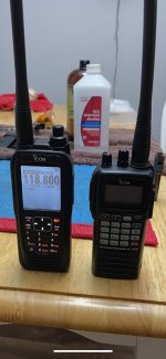
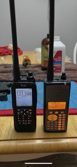
I do not need more handhelds.Easy answer! The “Motorola” of aviation handhelds, the Icom IC-A25.
Sure it’s expensive, because your life might depend on this. Reception on TX and RX is spectacular even with the stock antenna. Good to know if things go south. Even while transmitting an unusually large percentage of the battery cycle, the battery life is really really good. I’m pretty chilly WX too.
I use it while not in or around the aircraft, pick up the ATIS and of course as a back up radio to another backup radio. And of course, while at home or even at the airport watching other aircraft, I’ll use it as a scanner. Because it blows every other receiver out of the water on VHF-A.
Seriously I would then either get a BCD996T or BCT15X. They are basically the best base/m obile scanners for airI do not need more handhelds.
I am looking for as best as possible desktop/mobile solution which will extend my home setup.
Anyway thanks for your effort.
-m