Discriminator Tap

Status
Not open for further replies.
Joined
Dec 27, 2007
Messages
571
Location
Central AL
I'm wanting to add a discriminator tap to a Radioshack Pro-2050. I would've posted in the RS forum but this isn't really a question about this particular scanner. What wire do I need to use when I'm adding a tap to my scanner? I know I'll need a 3.5mm adapter to put at the end of my wire coming off of Pin 9, but I'm just unsure about how I need to go about doing this.

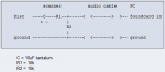
From what I've gathered it seems like I'm supposed to use some shielded wire and connect my audio wire to Pin 9 and the shield to a ground point in the scanner. That's where I get confused. I've found plenty of resources that tell where Pin 9 is, but none that actually give the basics like what kind of wire to use, etc. I've also heard people talk about using resistors in their tap, do I need to do that?
 

AJAT

Member
Premium Subscriber
Joined
Dec 1, 2008
Messages
435
Location
Navajo County AZ
I put a tap on my Pro 95. I used a short piece of speaker wire, grounded the outside of the audio jack, and soldered the inside of the jack to the discriminator tap. I did not use any resistors and it works well. I use it to decode Marine AIS.
 

n4yek

Member
Joined
Apr 20, 2004
Messages
2,506
Location
Newport, Tennessee
On my Pro 95 I used 2 pieces of 24 gauge wire for my tap, one to ground my jack to the pc board (plastic chassis) the other went from the jack to the discriminator tap. Also used a 10k ohm resister in line for protection to keep un-wanted grounding getting to the IC chip when I plug and unplug the connector.
 

kruser

Active Member
Premium Subscriber
Joined
Nov 25, 2007
Messages
4,989
Location
West St Louis County, MO
I'm wanting to add a discriminator tap to a Radioshack Pro-2050. I've also heard people talk about using resistors in their tap, do I need to do that?

Sometimes you do need a resistor and maybe a capacitor. It all depends on the way the radio is setup. The resistor/capacitor combo acts as a filter and can remove unwanted signals (usually a 455 kHz component) from the baseband audio signal. I find that a direct tap (no resistor or capacitor) does work in most cases however.
The addition of a resistor and/or capacitor can also help protect your radio in case you do something stupid on the outside like accidently plug in power to the output jack.
I'm not familiar with the 2050 though so I have no idea if any extra components are needed.
You can look at other models that use the same IF chip as the 2050 and see what is recommended for those. That may give you a good idea if a cap or resistor is a good idea or not.
Discriminator Output

Good Luck!

edit: I forgot to add that any short hunk of shielded audio cable will work fine for the wire from the tap point to your jack of choice. Ground the shield on at least one end and also make sure the shield is connected to the proper terminal on your jack. I've also seen a lot of taps that use a single unshielded wire running from the jack to the tap point. Those also need the ground terminal on the jack grounded to the radios board ground. I'd recommend using a shielded wire though or else it could pickup stay crud from the radios circuits.
A good type wire too use is the old audio wire that hooked from the back of a CD ROM drive to the motherboard. Those will have two shielded signal wires for the right and left channels and is small gauge so it is tiny.
 
Last edited:
Joined
Dec 27, 2007
Messages
571
Location
Central AL
Thanks for the tips guys! Since the back of my scanner is both metal and grounded to the chassis of the scanner I think I should be able to get by with just using a piece of shielded wire to the proper terminal on my jack. Since the jack will be mounted on the metal it should be grounded through that.

I think most of these radios use the same IF chip, but it just seems pretty varied as to whether or not they need caps and resistors. I need to go pick up a 3.5mm jack anyway, so I'll just go ahead and get some resistors and capacitors while I'm at it.
 

kruser

Active Member
Premium Subscriber
Joined
Nov 25, 2007
Messages
4,989
Location
West St Louis County, MO
I'd add a 5k to 10k resistor in series with your signal wire. That will help prevent any loading effect that the external device may place on the circuit in the radio. If the signal level appears low, try a 1k resistor instead. That should give a higher signal level at the new jack without lowering the needed signal by much.
For my needs at work, a true discriminator output into a sound card input did work but it still had errors as I moved a greater distance from the transmit antenna which caused a noisier signal. I then built a hardware interface (2 level) and that worked much much better I found.

A capacitor may also be used but "I think" they are generally used to form a filter and remove unwanted signals that may be riding along with the unfiltered audio. I think that you may need test equipment to determine if a capacitor is needed so try without.
 

W2PMX

Member
Joined
Oct 29, 2011
Messages
333
Location
Fayetteville NC
I think most of these radios use the same IF chip, but it just seems pretty varied as to whether or not they need caps and resistors.
No, they do. What's varied is the understanding of electronics of the various people who post the articles on adding a tap.

You use a large capacitor (.1uf will do) in series with the pin to protect the scanner against external voltages, and a 10k resistor in series/.002uf capacitor to ground after the resistor to eliminate 455 KHz signal. They're all needed. Many people get by without the first capacitor, or without either capacitor. Many get by with nothing but the wire. Many don't even use shielded wire. That doesn't mean that they aren't all needed.
 
Joined
Dec 27, 2007
Messages
571
Location
Central AL
I wound up using a piece of wire running from Pin 9 to the 3.5mm panel jack with a 10k resister in between them. This scanner cost me $2.50 and I'm happy to report that I'm now using DSD to decode a local P25 system. So it all worked out.

I've been putting this project off for a while and I finally decided to just go for it since I already have a Pro-96 and really had nothing to lose. Seems that it was a success!
 

kruser

Active Member
Premium Subscriber
Joined
Nov 25, 2007
Messages
4,989
Location
West St Louis County, MO
No, they do. What's varied is the understanding of electronics of the various people who post the articles on adding a tap.

You use a large capacitor (.1uf will do) in series with the pin to protect the scanner against external voltages, and a 10k resistor in series/.002uf capacitor to ground after the resistor to eliminate 455 KHz signal. They're all needed. Many people get by without the first capacitor, or without either capacitor. Many get by with nothing but the wire. Many don't even use shielded wire. That doesn't mean that they aren't all needed.

I like this. Nice and easy to understand plus it explains the theory behind the r/c filter.
I agree that a lot of articles exist that are wrong.
Would you also agree that adding the r/c filter is a good idea even if there claims to be no 455 kHz signal on the wire? I see no harm in trying to filter something thay may or may not exist. Better to be safe than sorry in my book.
Plus, like you mentioned, the lage cap also blocks external DC from getting back into the radio which is good insurance and cheap too.
 

W2PMX

Member
Joined
Oct 29, 2011
Messages
333
Location
Fayetteville NC
Would you also agree that adding the r/c filter is a good idea even if there claims to be no 455 kHz signal on the wire? I see no harm in trying to filter something thay may or may not exist.
Exactly. The filter has just about no effect on the frequencies you're interested in.
quote]Better to be safe than sorry in my book.[/quote]It's not "sorry". If there's 455 mixed in with the signal, it's either high enough level to keep the decoder from working (in which case you just add the filter) or it's not, in which case you don't worry how much there is. This is reality, not the final exam in an AC theory course.
Plus, like you mentioned, the lage cap also blocks external DC from getting back into the radio which is good insurance and cheap too.
Yes - but that has nothing to do with filtering (except for "filtering" DC). Any cap small enough to have any effect on audio frequencies is too small. The ideal DC blocking cap is infinite capacity (which would give a cutoff frequency of 0Hz), but a .1uf is large enough in this case, and it's small and cheap.
 

kruser

Active Member
Premium Subscriber
Joined
Nov 25, 2007
Messages
4,989
Location
West St Louis County, MO
Yes - but that has nothing to do with filtering (except for "filtering" DC). Any cap small enough to have any effect on audio frequencies is too small. The ideal DC blocking cap is infinite capacity (which would give a cutoff frequency of 0Hz), but a .1uf is large enough in this case, and it's small and cheap.
I understand that part well. I meant to say the dc blocking cap is cheap insurance against inadvertently sending DC back into the radio. I kind of lumped that comment in with the filter circuit comment.

Hopefully others getting ready to perform a discriminator tap will see this info and learn from it.
 

kruser

Active Member
Premium Subscriber
Joined
Nov 25, 2007
Messages
4,989
Location
West St Louis County, MO
Wow, the misinformation train never stops...

A 0.1uF cap will absolutely trash low speed data (LTR, etc.)

So... if W2PMX's 0.1uf is incorrect, what value do you recommend or do you recommend no dc blocking cap?

As I stated earlier, I've often done this with just a resistor and sometimes the entire r/c filter if I found a stray signal but I think it was rare that I used any form of dc blocking cap (at least not on a discriminator tap circuit).
 

pro92b

Mutated Member
Premium Subscriber
Joined
Jun 27, 2002
Messages
1,908
So... if W2PMX's 0.1uf is incorrect, what value do you recommend or do you recommend no dc blocking cap?

As I stated earlier, I've often done this with just a resistor and sometimes the entire r/c filter if I found a stray signal but I think it was rare that I used any form of dc blocking cap (at least not on a discriminator tap circuit).

It depends on what the discriminator tap is connected to. Back in the days when data slicers ruled the high input impedance of the slicer allowed the use af fairly high resistance in the tap feed. Since the slicer almost always has an input cap, none was needed in the radio from the tap point.

Now that the tap is more likely to be connected to a computer sound card the situation has changed. The sound card input is probably lower impedance and may have a cap to ground for noise or RF suppression.

When I connected my tapped PRO-2006 to both a data slicer and sound card the data slicer began losing decoding accuracy. The radio had a 10K resistor in the tap feed and the sound card was loading down the signal from the radio.

I measured the input at the sound card (Thinkpad 600X) when fed with a 10K resistor from an audio generator. The signal cut in half and the high frequencies were attenuated. Using a frequency sweep, the sound card input impedance was calculated to be about 13K in parallel with a .01uF cap.

To transfer a wideband signal to the sound card the tap resistor needs to be reduced to 1K or less. If a cap is to be placed in the tap feed, at 1uF the low cut off frequency is about 12 Hz. This is as high as I would like to see, and I would probably recommend 2.2uF to push the cut off lower. The capacitor should be non polar if there is concern about 12 volts accidently being connected to the tap point. The Nichicon ES series is bipolar and would be suitable.

Putting a resistor in the tap feed limits the current into or out of the IF chip and it is good practice to include one. The cap prevents steady state DC current in both directions but does not block transient current that might arise when something is connected to the tap. The resistor limits transient current in this case.

Bottom line: for sound card connections use 1K and 2.2uF in series from the tap point. Do not place a cap from the discriminator jack to ground. There probably already is a cap in the sound card input circuit.
 
Joined
Dec 27, 2007
Messages
571
Location
Central AL
Alright everyone, my tap is working fine but the Pro-2050 can't store more than 30 frequencies for a trunking system. This means I can't program in all of my agency's frequencies into it. I guess I'll have to add a tap to my BC246T as well which will let me do that. At least if any agencies near me ever start using TRBO I can use the 2050 to monitor that.
 

slicerwizard

Member
Joined
Sep 19, 2002
Messages
7,643
Location
Toronto, Ontario
So... if W2PMX's 0.1uf is incorrect, what value do you recommend or do you recommend no dc blocking cap?
I've tried it both ways and all audio signals look the same on a PC with or without a (decent sized) cap. However, good engineering practice would be to add a cap, since both discriminator circuits and sound card inputs have DC voltages present, and there is no good reason to combine them. I use 10uF tantalum caps because they're small and their large capacitance guarantees good low frequency response / no signal distortion.

Datastreams can have long runs of consecutive symbols; that puts very low frequency components on the audio stream. For example, PassPort low speed data can have at least 16 zeroes or ones in a row; Motorola control channels can have more than 30. Undersized caps can't properly pass that audio and leave you reliant on software developers' abilities to clean up a problem that you can eliminate yourself. So go big...


As I stated earlier, I've often done this with just a resistor and sometimes the entire r/c filter if I found a stray signal but I think it was rare that I used any form of dc blocking cap (at least not on a discriminator tap circuit).
A minimal interface (e.g. one resistor) generally leads to some signal distortion. How much generally depends on the specific PC sound hardware. I find that the cheap ($2) USB sound cards that you can get on eBay and DealExtreme that look like this one

USB Sound Card Adapter (3D 5.1ch) - Rs.300.00 : Gadget Lanka Online Store, Cheapest Online Gadget Store in Sri Lanka

are particularly fussy and want to see an interface with a proper voltage divider like so:

tap --- 10uF --- ~10k ---+--- ~10k --- ground

(+ marks center of divider and goes to PC sound input)


If you're looking to decode four level data, don't scrimp on your interface. If you ever want more inputs than just your PC/laptop's onboard sound, those USB devices are dirt cheap and work just fine if you have proper tap interfaces in your radios.

BTW, a friend had a good idea - those USB devices are so cheap that it makes sense to just put them inside any mobile radios that you tap and just run USB cables to your PC/laptop(s) instead of audio cables. The plastic shells pop right off and you can solder your tap components directly to the devices' audio inputs, rather than using their audio jacks.

And since your audio interfaces are optimally tweaked for the USB devices, you now have taps that will work consistently no matter what PCs you connect them to. Of course, using the USB devices externally gets you the same benefit - you can move them between computers and still have consistent audio quality.
 

Comint

Member
Premium Subscriber
Joined
May 21, 2003
Messages
630
Location
Queensland, Australia
. . are particularly fussy and want to see an interface with a proper voltage divider like so:

tap --- 10uF --- ~10k ---+--- ~10k --- ground

(+ marks center of divider and goes to PC sound input)
Something along the lines of the attached image.

--
Comint
 

Attachments

  • Discriminator_Tap.png
    Discriminator_Tap.png
    6.6 KB · Views: 2,297

davidmc36

Member
Premium Subscriber
Joined
Nov 14, 2004
Messages
1,861
Location
South East Ontario
I've tried it both ways and all audio signals look the same on a PC with or without a (decent sized) cap. However, good engineering practice would be to add a cap, since both discriminator circuits and sound card inputs have DC voltages present, and there is no good reason to combine them. I use 10uF tantalum caps because they're small and their large capacitance guarantees good low frequency response / no signal distortion.

Datastreams can have long runs of consecutive symbols; that puts very low frequency components on the audio stream. For example, PassPort low speed data can have at least 16 zeroes or ones in a row; Motorola control channels can have more than 30. Undersized caps can't properly pass that audio and leave you reliant on software developers' abilities to clean up a problem that you can eliminate yourself. So go big...


A minimal interface (e.g. one resistor) generally leads to some signal distortion. How much generally depends on the specific PC sound hardware. I find that the cheap ($2) USB sound cards that you can get on eBay and DealExtreme that look like this one

USB Sound Card Adapter (3D 5.1ch) - Rs.300.00 : Gadget Lanka Online Store, Cheapest Online Gadget Store in Sri Lanka

are particularly fussy and want to see an interface with a proper voltage divider like so:

tap --- 10uF --- ~10k ---+--- ~10k --- ground

(+ marks center of divider and goes to PC sound input)


If you're looking to decode four level data, don't scrimp on your interface. If you ever want more inputs than just your PC/laptop's onboard sound, those USB devices are dirt cheap and work just fine if you have proper tap interfaces in your radios.

BTW, a friend had a good idea - those USB devices are so cheap that it makes sense to just put them inside any mobile radios that you tap and just run USB cables to your PC/laptop(s) instead of audio cables. The plastic shells pop right off and you can solder your tap components directly to the devices' audio inputs, rather than using their audio jacks.

And since your audio interfaces are optimally tweaked for the USB devices, you now have taps that will work consistently no matter what PCs you connect them to. Of course, using the USB devices externally gets you the same benefit - you can move them between computers and still have consistent audio quality.
So what you say here about mounting the USB sound cards inside the radio should answer this question.

I could run a short wire form the tap point to the USB device and put the components there. Then maybe just change the USB connector on the sound device so I can plug a mini usb cable into it. Mount it all on some perf board and attach inside with holes in the case to plug cables in.
 

kruser

Active Member
Premium Subscriber
Joined
Nov 25, 2007
Messages
4,989
Location
West St Louis County, MO
So what you say here about mounting the USB sound cards inside the radio should answer this question.

I could run a short wire form the tap point to the USB device and put the components there. Then maybe just change the USB connector on the sound device so I can plug a mini usb cable into it. Mount it all on some perf board and attach inside with holes in the case to plug cables in.

I think that sounds like a great idea!
I have like 2 dozen of those cheapo usb sound dongles here and this is a perfect use for them! I think I'd test them first before you go to the trouble of mounting them however. I had two dead ones out of my original batch of 12. One was dead on the audio input side and the other on the usb side. I never did pop them open and see if it was just poor soldering.
I later bought another batch of 16 and have not found a dead one yet but I'll admit that I never tested all in that second batch.

I guess the smart thing to do would be to tap your radio and make sure the tap produces good results using the el cheapo usb sound card of choice and whatever you are decoding. Then when it all works, stick it on a perfboard or something and wire it to your choice of mini or micro or standard usb jack that you have mounted on the scanner chassis.

I wonder if these devices can put out any RFI that may be picked up by the scanners circuitry? Hopefully everything in them is well below 25 MHz.
I guess you could setup a search across the scanners entire range and then run that with no antenna, unplug the el cheapo sound card each time the scanner stops on something and confirm if it is the usb dongle or just a normal birdie.
If enough noise is found coming from the usb sound dongle, maybe the entire perfboard can be enclosed so it is shielded. You could use PC board making material that has at least one side covered with solid copper clad and then cut yourself sides and solder those to the main board the dongle is resting on. Then the last step would be to solder on a lid. Of course you would need two small or one larger opening for the signal in and usb control cables to get into the little box you built. Maybe a couple ferrite beads or chokes over the USB control cable to the device. A 43 material is good for reducing RFI up to about 400 MHz and then if you find unwanted crud even higher, the 64 material is good at suppressing noise up too 1GHz. I would think the 43 material is more than adequate though as I doubt those little sound dongles would emit any noise much higher than 100 Mhz if even. I bet most noise is going to be below 25 MHz which could get into an IF stage. For noise that may get into IF stages below 50 MHz, a 73 or 77 material are both good for about 0.5 MHz up to 50 MHz.

In the least, where you are working in tight spaces, I'd mount the sound dongle on a single sided copper clad board so it offers some shielding between the sound dongle and the scanners board. Just leave the sides and top off for space savings.
Or you could wrap the whole thing once wired with some super thin copper or tin sheet and solder it shut. That would need to be insulated so the shield does not short against something on the scanners board.
Just the other day I bought some super thin brass sheets about 4 inches wide by 9 inches long. It is just heavier than the super heavy duty aluminum foil you can buy so it is very workable and you can darn near crumble it into a ball if you wanted too. Plus being brass, it is solderable so it would be a perfect material for making a tight fitting shielded enclosure for a sound dongle if you find that your dongle produces unwanted noise when powered up.
 

vans113

Member
Premium Subscriber
Joined
Jul 10, 2012
Messages
418
Location
Tennessee
I used plain jane speaker wire for my tap shielded of course, and a 10k ohm resistor i got from radio shack,and i grounded it to a screw on the outside of my scanner.
 
Status
Not open for further replies.
Top