FM bandstop filter comparison

Status
Not open for further replies.

dlwtrunked

Member
Premium Subscriber
Joined
Dec 19, 2002
Messages
2,394
I measured some of my filters a while back (I did not keep the measurement for the Digikey as it was so deep, it was in the noise but it was the best filter for depth and bandwidth).

Archer (RadioShack) and similar 86.3-113.9 87.6-115.7
PAR 82.2-114.2 83.9-112.5
Stridsberg 71.7-130.8 74.7-126.8

One thing to look out for is that some filters seem to have additional significant unplanned notches in the 700-1000 MHz range. One should check up there when installing notch filters for other bands by inserting and removing the notch while monitoring signals cared about in the 700-1000 MHz range.
 

Ubbe

Member
Joined
Sep 8, 2006
Messages
9,785
Location
Stockholm, Sweden
I would recommend to use stub filters only as a test and then get a proper filter, if you would like to keep the upper frequency bands intact.
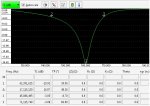
I sweeped a lenght of RG6 coax that seemed to correspond to a 62MHz stub filter just to see what happens at higher frequencies.

Stub bandwidth.jpg

Stub.jpg
Stub SWR.jpg

/Ubbe
 

dlwtrunked

Member
Premium Subscriber
Joined
Dec 19, 2002
Messages
2,394
I measured some of my filters a while back (I did not keep the measurement for the Digikey as it was so deep, it was in the noise but it was the best filter for depth and bandwidth).

Archer (RadioShack) and similar 86.3-113.9 87.6-112.4
PAR 82.2-114.2 83.9-112.5
Stridsberg 71.7-130.8 74.7-126.8

One thing to look out for is that some filters seem to have additional significant unplanned notches in the 700-1000 MHz range. One should check up there when installing notch filters for other bands by inserting and removing the notch while monitoring signals cared about in the 700-1000 MHz range.

Something got dropped as the RR editing does not work right when I try doing tables. The first numbers above are the -6 dB notch bandwidth and the second are the -50 dB notch bandwidth. I corrected also a typo in one of the numbers (115.7 should have been 112.4 as corrected above).
 

dlwtrunked

Member
Premium Subscriber
Joined
Dec 19, 2002
Messages
2,394
Here are plots. Note: I use a Digikey filter but have not located my measurements for it but recall it was superior to these in all regards (bandwidth width, placement, and notch depth).FM compare.jpg
 
Last edited:

dlwtrunked

Member
Premium Subscriber
Joined
Dec 19, 2002
Messages
2,394
I wanted to emphasize again that I have observed some of the FM traps to have notches and attenuation about 700 MHz but that was not the case with the Digikey. Off-topic but related, the Stridsburg multi-coupler has about -6 dB or more attenuation at 1 GHz and higher, so one does not want to use that on an antenna for ADS-B.
 

pro92b

Mutated Member
Premium Subscriber
Joined
Jun 27, 2002
Messages
1,960
Do you have a part number for the DigiKey filter? Do they still sell it?
 

pro92b

Mutated Member
Premium Subscriber
Joined
Jun 27, 2002
Messages
1,960
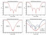
I used Excel to plot the detailed data for the ZBSF-95+ as published by Mini-Circuits. The plots are typical insertion loss at 25C. The second plot shows the trade-off they made regarding attenuation at the top of the FM band vs. chopping the lower part of the civil air band.

Clipboard01.gifClipboard02.gif
 

prcguy

Member
Premium Subscriber
Joined
Jun 30, 2006
Messages
16,635
Location
So Cal - Richardson, TX - Tewksbury, MA
What I really want is a high pass filter with 60dB+ attenuation of 108MHz and below and .25dB loss from 118 to 512Mhz. That should be doable but it would be expensive in small qyts.

@prcguy ..

You might be lucky at the bottom of the band with the flamethrower at 88.1. My thought is that *additional* attenuation beyond the mini-circuits filter, and open-ended quarter-wave stub at the input to your desired receiver (made from GOOD coax/hardline) might provide a bit of additional attenuation without the insertion loss starting to affect the bottom of the vhf air-band.

If the flamethrower was at 107 mhz, nah, I probably wouldn't try the addition of a stub after the filters.. But at 88.1 - maybe...
 

vagrant

ker-muhj-uhn
Premium Subscriber
Joined
Nov 19, 2005
Messages
3,437
Location
California
nanZor, is good quality coax important for a stub, or knowing the velocity factor of whatever coaxial cable one would use in order to determine the length? Would one be better served using LDF4-50A over say RG58 when creating a stub, if so why? What are the losses further up and down from the target frequency using a stub made for 88.1 MHz and the tee connecting it?
 

prcguy

Member
Premium Subscriber
Joined
Jun 30, 2006
Messages
16,635
Location
So Cal - Richardson, TX - Tewksbury, MA
As Ubbe hinted, a stub filter will also suck out odd harmonic frequencies. Make one for 88.1MHz and it will also take out 264.3MHz and 440.5MHz and so on. The size and quality of coax will affect the Q of the filter with RG-58 giving a wider notch and 7/8 hardline giving a narrower notch with more depth. This type of filter can affect frequencies many MHz away from the target frequency.

The higher the velocity factor the longer the coax will be for a particular frequency. If the velocity factor was 100% then the coax length would be a full 1/4 wavelength in free space. Older solid dielectric coax can have a velocity factor around 60% leaving the coax length about 60% of a free space 1/4 wavelength. 7/8"Heliax has a velocity factor around 89% which would leave you with a longer coax compared to RG-213, etc.

nanZor, is good quality coax important for a stub, or knowing the velocity factor of whatever coaxial cable one would use in order to determine the length? Would one be better served using LDF4-50A over say RG58 when creating a stub, if so why? What are the losses further up and down from the target frequency using a stub made for 88.1 MHz and the tee connecting it?
 
Last edited:

nanZor

Active Member
Joined
May 28, 2009
Messages
2,807
prcguy is spot on in regards to odd harmonics, and the need for high-quality coax/hardline to keep the notch sharp.

I was thinking along the line of just using it for an airband application, and where the odd harmonic in the mil-air band might not be an issue.

But back to the filters, plenty of stub threads already...
 

dlwtrunked

Member
Premium Subscriber
Joined
Dec 19, 2002
Messages
2,394
I wanted to emphasize again that I have observed some of the FM traps to have notches and attenuation about 700 MHz but that was not the case with the Digikey. Off-topic but related, the Stridsburg multi-coupler has about -6 dB or more attenuation at 1 GHz and higher, so one does not want to use that on an antenna for ADS-B.
As posted elsewhere, I meant Mini-Circuits not Digikey.
 

dlwtrunked

Member
Premium Subscriber
Joined
Dec 19, 2002
Messages
2,394
As some caught, I meant Mini-Circuits not Digikey. I noticed the typo too late for RR to let me change it.
 

scanmanmi

Member
Premium Subscriber
Joined
Sep 25, 2011
Messages
841
Location
Central Michigan
Why do you need a trap? What are the symptoms? Is there a rule of thumb about how far away an FM station has to be before it's a problem?
 

jonwienke

More Info Coming Soon!
Joined
Jul 18, 2014
Messages
13,409
Location
VA
That totally depends on terrain, TX power, the station's antenna configuration, and your receiver's selectivity.
 

devicelab

Whacker Extraordinaire
Joined
Jul 18, 2016
Messages
1,673
Location
Nowhere in WA
I'm late to this party but IMHO the RTL-SDR is the best performer, IMHO. I have a trouble-station at the 105 Mhz mark and so I need the insertion loss highest at the top-end of the band. I could care less about 118 Mhz so I'd rather it shift upward than downward.

I couldn't do any tests on my filters w/o a proper SA or VNA but I finally got one recently. Here's the RTL-SDR and the GPIO at the bottom. The GPIO is better for the lower portion of the band.

RTLSDR-FMTRAP.JPG


GPIO-FMTRAP.JPG
 

vagrant

ker-muhj-uhn
Premium Subscriber
Joined
Nov 19, 2005
Messages
3,437
Location
California
I'm late to this party but IMHO the RTL-SDR is the best performer, IMHO. I have a trouble-station at the 105 Mhz mark and so I need the insertion loss highest at the top-end of the band. I could care less about 118 Mhz so I'd rather it shift upward than downward.
Indeed! That is why I posted the numbers to start this thread. Everyone's needs are not the same wherever they are in the world. For your needs the RTL-SDR filter is the best performer for you and I'm sure others. The point of this thread is for people to consider that a nearby broadcast station pushing thousands of watts could definitely hinder their hobby. A relatively inexpensive filter can help, or a $100 filter may address one's specific needs better. By having the numbers, people can make an informed decision and spend their money wisely.

Thank you for sharing.
 

prcguy

Member
Premium Subscriber
Joined
Jun 30, 2006
Messages
16,635
Location
So Cal - Richardson, TX - Tewksbury, MA
The RTL-SDR is not the best performer, it ruins most of the VHF air band. Anyone can make a filter that attenuates the FM broadcast band by 50-60dB, the trick is not to affect anything within a few MHz of the FM broadcast band. As mentioned, what is good for you is not good for everyone else.

I'm late to this party but IMHO the RTL-SDR is the best performer, IMHO. I have a trouble-station at the 105 Mhz mark and so I need the insertion loss highest at the top-end of the band. I could care less about 118 Mhz so I'd rather it shift upward than downward.

I couldn't do any tests on my filters w/o a proper SA or VNA but I finally got one recently. Here's the RTL-SDR and the GPIO at the bottom. The GPIO is better for the lower portion of the band.

RTLSDR-FMTRAP.JPG


GPIO-FMTRAP.JPG
 
Status
Not open for further replies.
Top