I am new to Mini-Circuits - Can you answer a few questions?

Facsimile

Member
Premium Subscriber
Joined
Apr 8, 2023
Messages
78
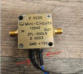
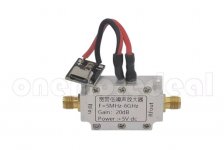
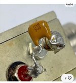
I've been looking at Mini-Circuits recently and would like to start experimenting with some. I have a few questions about the following three pictures:

  • Question 1: Picture 1 has a USB type C connector. Is this a valid way to permanently power an indoor-only device? What would be a good alternative if it were outside and the bias T route was not available?
  • Question 2: Picture 1 and 3 have really nice connections to the V+ and GND terminals. Is that just heat shrink? Or some other material?
  • Question 3: In Picture 2, there appears to be a ?capacitor? between the V+ and GND terminals. What is the purpose of this? I've noticed it being used in many online used listings.
  • Question 4: What gauge wire would you recommend using for 5v? I have various amounts lying around.
  • Question 5: I noticed that in a few of the datasheets that I read, there is a very narrow window for voltage changes without destroying the internal components. If I go the USB type C route, how can I best prevent the variable output besides using high quality name brand power bricks?

Thanks :)
111.jpg222.jpg333.jpg
 

prcguy

Member
Premium Subscriber
Joined
Jun 30, 2006
Messages
16,119
Location
So Cal - Richardson, TX - Tewksbury, MA
I've been looking at Mini-Circuits recently and would like to start experimenting with some. I have a few questions about the following three pictures:

  • Question 1: Picture 1 has a USB type C connector. Is this a valid way to permanently power an indoor-only device? What would be a good alternative if it were outside and the bias T route was not available?
  • Question 2: Picture 1 and 3 have really nice connections to the V+ and GND terminals. Is that just heat shrink? Or some other material?
  • Question 3: In Picture 2, there appears to be a ?capacitor? between the V+ and GND terminals. What is the purpose of this? I've noticed it being used in many online used listings.
  • Question 4: What gauge wire would you recommend using for 5v? I have various amounts lying around.
  • Question 5: I noticed that in a few of the datasheets that I read, there is a very narrow window for voltage changes without destroying the internal components. If I go the USB type C route, how can I best prevent the variable output besides using high quality name brand power bricks?

Thanks :)
1. USB can provide a reliable 5v to a bias T but it can have RF noise on it that can travel to the antenna system powered by the bias T.

2. Thats heat shrink covering the solder connections.

3. That is a bypass capacitor across the voltage input to help keep unwanted RFI out of the bias T and whatever it's feeding. Typical values are .1uf to .001uf depending on target frequency range.

4. 22ga to 24ga should be fine, bias Tees don't usually pass more than a few hundred ma.

5. I would expect USB in general to supply a very constant voltage except when powering a computer on and off. I would use something else like a well regulated linear (not switching) wall wart type power supply, A good linear wall wart supply is usually well isolated from the AC mains due to the internal transformer design with separate bobbins for primary and secondary windings and that helps keep RFI on the AC mains from passing through the power supply on to whatever your feeding with the bias T.
 
Top