• To anyone looking to acquire commercial radio programming software:

    Please do not make requests for copies of radio programming software which is sold (or was sold) by the manufacturer for any monetary value. All requests will be deleted and a forum infraction issued. Making a request such as this is attempting to engage in software piracy and this forum cannot be involved or associated with this activity. The same goes for any private transaction via Private Message. Even if you attempt to engage in this activity in PM's we will still enforce the forum rules. Your PM's are not private and the administration has the right to read them if there's a hint to criminal activity.

    If you are having trouble legally obtaining software please state so. We do not want any hurt feelings when your vague post is mistaken for a free request. It is YOUR responsibility to properly word your request.

    To obtain Motorola software see the Sticky in the Motorola forum.

    The various other vendors often permit their dealers to sell the software online (i.e., Kenwood). Please use Google or some other search engine to find a dealer that sells the software. Typically each series or individual radio requires its own software package. Often the Kenwood software is less than $100 so don't be a cheapskate; just purchase it.

    For M/A Com/Harris/GE, etc: there are two software packages that program all current and past radios. One package is for conventional programming and the other for trunked programming. The trunked package is in upwards of $2,500. The conventional package is more reasonable though is still several hundred dollars. The benefit is you do not need multiple versions for each radio (unlike Motorola).

    This is a large and very visible forum. We cannot jeopardize the ability to provide the RadioReference services by allowing this activity to occur. Please respect this.

XTL/XTS5000 Not powering on with W4 dash mount head

KD9RTX

Member
Joined
Apr 27, 2022
Messages
106
I bought a cheap XTL5000 brick to tinker with a while back and just got the rest of the parts I need to configure it as a dash mount. I'm able to power it on by jumping pins 20 and 22 on the TIB connector and I can read/write the radio using Mobile CPS 20. The problem I'm having is that it wont power up using the W4 control head I bought on eBay. (yeah, I know, you pays your money and you takes your chances) It came with what should be the proper dash mount flex (3085020F01) and I was able to change the control head model in the code plug from W7 to W4 to match the one I bought. When I turn the volume knob on nothing happens. I even tried the dimmer button to make sure the brightness wasn't all the way down and I've tried reading the radio with no luck. As soon as I plug the TIB back in with pins 20 and 22 jumped and apply power I am able to read the radio. Ignition switch is set to blank in the code plug and it powers on just fine without 12V to the ignition sense line.

That's what I've tried so far. Are there any settings I may be missing that might be causing this or did I just buy a lemon?
 

wgbecks

Active Member
Joined
Jan 17, 2005
Messages
974
Location
NE Wisconsin
Please confirm that you are converting the radio from a "Remote Mount" by removing the TIB that came with the radio and
are replacing it with the W4 as a "Dash Mount" using the indicated dash flex and headbridge? If so, are you sure you have
correctly installed (seated) the flex cable on both ends?
 

KD9RTX

Member
Joined
Apr 27, 2022
Messages
106
Installed on the radio when I bought it: HLN6883C TIB, 30850119F01 remote mount flex, 1585245E01 headbridge

Purchased: AAHN4045E W4 head, 3085020F01 REV0 DC1904 dash mount flex, 1585245E01 headbridge

All pins for the flex connection appear to be intact and none are bent. Flex cables have seated in their sockets with the usual amount of force, never felt anything unusual when installing them and nothing appears damaged.
 

wgbecks

Active Member
Joined
Jan 17, 2005
Messages
974
Location
NE Wisconsin
I would need to look at the W4 control head schematic to comment on troubleshooting checks. Do you still have a cable attached to the
rear accessory connector (J2) now that the W4 control head is connected? Have you carefully examined the flex cable looking for any
signs of breaks or cracks in any of the conductors?
 

KD9RTX

Member
Joined
Apr 27, 2022
Messages
106
Yep, same rear programming cable I've used with my working XTL2500. That cable stayed in place throughout the tinkering. I also tried the normal accessory cable/connector with no luck. It also works on the 2500 so it shouldn't be that.

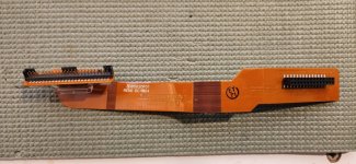
The flex looks pristine. No signs of breaks. Unfortunately I don't have an extra flex to try.
 

wgbecks

Active Member
Joined
Jan 17, 2005
Messages
974
Location
NE Wisconsin
On the W4 Control Heads, there are a number of jumpers used to set various options. It might be that your particular control head
was optioned for ignition switch control. I am almost sure that you have to satisfy the correct jumper option and don't believe that
the Ignition switch setting in CPS applies to this hardware configuration. I would have to buzz out the schematics to know how all
of this applies to using the W4 with the XTL series.

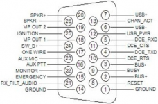
However, it's easy enough to put the theory to the test. Connect the Ignition Sense wire on Pin-25 of the rear accessory connector
to a fused +12 VDC power source and see if the radio will turn on/off with the rotary knob on the front of the W4.


W4 Power Options.png
 
Last edited:

wgbecks

Active Member
Joined
Jan 17, 2005
Messages
974
Location
NE Wisconsin
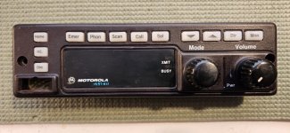
I may have been looking at the wrong control head manual. Does your W4 have ASTRO printed on it in the upper left corner?
 

KD9RTX

Member
Joined
Apr 27, 2022
Messages
106
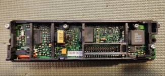
It has Astro printed in the lower left corner of the screen. No obvious jumpers that I can see on the back. Here are pictures of the control head and flex. I should have posted these in the first place.

20230625_170413.jpg
20230625_170423.jpg
20230625_170446.jpg
 

a417

Active Member
Joined
Mar 14, 2004
Messages
4,669
The jumpers in moto radios are not the ones you might be used to seeing on a PC motherboard. They are usually 0 ohm resistors across two pads (or arrays of pads). There is no traditional header you might be accustomed to looking for.
 

KD9RTX

Member
Joined
Apr 27, 2022
Messages
106
I suspected as much when I didn't see the typical header jumper on the back. I did notice a couple of 0 ohm surface mount resistors though but I haven't taken a look at the schematic. I tried hooking up the ignition wire but didn't have any luck with that either.
 

wgbecks

Active Member
Joined
Jan 17, 2005
Messages
974
Location
NE Wisconsin
Sorry, we were away for several hours this afternoon and I am just now getting a chance to follow up. I stand corrected, the word "Astro" should and does appear in the lower left of the display area as pictured in Post # 8. Yes, the jumpers are 0 ohm SMD resistors as pointed
out by @a417. Does your program or regular 26-Pin connector cable contain the "Red" Ignition switch wire?
 

wgbecks

Active Member
Joined
Jan 17, 2005
Messages
974
Location
NE Wisconsin
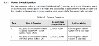
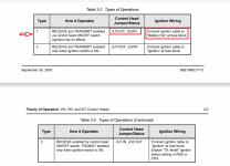
Reference Table 3-2 (below) that spells out that "Ignition" (Pin-25) of the Rear Accessory Connector (Dash Mount) must be connected
to a +12 VDC power source for any of the three options types listed in the table.

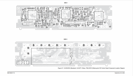
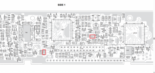
Verity that the Jumper JU1 is "Out" and that Jumper JU2 is "In" on the W4's printed circuit board at the locations highlighted in the
graphics shown below Table 3.2.

It appears from your photos that you will only need to insure that power is applied to Ignition (Pin-25) and your radio should come to life.

1687739229225.png

Jumper Table.png


OVERVIEW OF W4 PCB COMPONENT LAYOUT
W4 PCB.png
LOCATIONS OF JUMPERS JU1 & JU2 HIGHLIGHTED BELOW
JU1-JU2.png
 
Last edited:

KD9RTX

Member
Joined
Apr 27, 2022
Messages
106
So I have an update and will explain how I was an idiot. So I had previously tried the ignition wire hooked to a 12v source with no luck. But here's the kicker, I had attached it to a 12v battery I had handy since all of my power poles were used. Some of you playing at home can probably see where this is going. Of course that wouldn't work. It eventually occurred to me that it needed to be connected to the same power supply so that there is a common ground. So I unplugged one of my other radios, rigged up something ugly but effective to get 12v where I needed it to go, plugged the W4 head back in and it fired right up.

Many thanks for all of the advice and the circuit board diagrams. If I get the itch I might remove one of those resistors or just rig up a 12v ignition line and save the control head from my rudimentary soldering skills.
 
Top