It is at the very bottom right of the circuit board. There are two copper strips and at the bend it looks like a open circuit. The three battery holder connections are on the left bottom of the board and the strips are at the right bottom. You show the three battery holder terminals at the right of the board and this at the right off the board and is the bottom strip at the corner just before it goes into or under the diode.@kb3isq I'm looking for what you're talking about, and can't seem to find what you're describing. Is it on the side of the scanner where you can see the blue blocks of the squelch and volume/power knobs, or on the other side where you can see the contacts soldered through the board?
Perhaps you could post the exact picture you're talking about, and I could take a better one?

You are using an out of date browser. It may not display this or other websites correctly.
You should upgrade or use an alternative browser.
You should upgrade or use an alternative browser.
- Status
- Not open for further replies.
If your getting power to the switch, then it seems it's not battery / ext powered related. There should be a schematic out there somewhere for that radio and for the pro 95. (Same radio, just 1000 channel model) If you can find either, you may get somewhere. I did a quick search and came up empty.
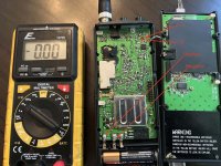
Ok, I think I see what you're talking about. I took a better picture to get up close, but I think that's just a bit of glue where they put down that D2531 component.It is at the very bottom right of the circuit board. There are two copper strips and at the bend it looks like a open circuit. The three battery holder connections are on the left bottom of the board and the strips are at the right bottom. You show the three battery holder terminals at the right of the board and this at the right off the board and is the bottom strip at the corner just before it goes into or under the diode.

If you are asking about the External Jack, yes, the center connection is + as marked clearly on the case "Pwr DC 9V".gmclam, I don't have a PRO-95. Can you please verify that the (+) power goes to the center of the connector? Thanks! rsparkyc, please take your meter and verify that you have 9v DC with (+) on the center of the connector of the AC power adapter. It wouldn't surprise me to see excessive voltage or polarity reversed on the adapter.
I think that's just a bit of glue where they put down that D2531 component.
When I see stuff like that I take a Q tip with a little circuit board cleaner or alcohol and clean it. I had a body control module that had something similar and when there was high moisture in the air, it seemed to become conductive and the windows would work intermittently and the door locks would cycle by themselves.
Holy cow. I jumped connections in that area and that totally did it. Oh my gosh you are amazing.When I see stuff like that I take a Q tip with a little circuit board cleaner or alcohol and clean it. I had a body control module that had something similar and when there was high moisture in the air, it seemed to become conductive and the windows would work intermittently and the door locks would cycle by themselves.

Here's the circuit. Q25 is for charging. Unregulated power is top line. 3.5 volts on pin 3 of each IC13 & IC14. Note that you could measure power to battery negative and it will look good but the unit won't power if L30 is open. I'd perform my voltage measurements from a good ground in the radio, not battery negative. BNC (antenna) outer connection goes directly to ground.
tvengr
Well Known Member
Thank you!If you are asking about the External Jack, yes, the center connection is + as marked clearly on the case "Pwr DC 9V"
Any kind of foreign substance or corrosion on a circuit board can be conductive. It can cause complete failure of operation such as preventing a scanner from booting up (appear dead). It can also cause weird things to happen. I had a video tape deck come into the shop that one of the editors had spilled a soft drink into. You could sit and watch the deck play, fast forward, and rewind all by itself. It took extensive cleaning of the circuit boards to fix the problem.When I see stuff like that I take a Q tip with a little circuit board cleaner or alcohol and clean it.
In this case, I think the glue may have come loose, actually damaging the board. I think I isolated where I can re-solder to bypass the damaged area. I think I can just go from the positive battery terminal to one side of the power switch. (Though it's weird that the power switch seemed to be getting power earlier...) I have tested that I'm not shorting over the power switch, when I jump over the affected area with the unit turned off, it still stays off.
tvengr
Well Known Member
If a foil has a break in it, you can just solder a thin piece of solid wire across the break.
tvengr
Well Known Member
If the keypad doesn't work, the unlock function probably doesn't work either. Keypads are usually scanned by polling a matrix. The keys are in rows and columns. When you press a button, the button is determined by where the row and column cross. With all the problems you are having, I would take a close look at the circuit boards. The leakage paths between foils caused by foreign substances and corrosion could easily be causing your problems. A little cleaning may be the answer. I would also check for cold and broken solder connections. Bad solder connections on circuit boards tend to show up after about 10 or 15 years. Putting a little pressure on or gently flexing a circuit board will often cause a bad connection to show up or disappear. The same is also true for microscopic cracks in foils.

tvengr
Well Known Member
What is the white on the circuit board?
I held my phone in front of a lamp for added light, so it's the reflection of the lamp behind it. Here's a more "natural" photo:What is the white on the circuit board?

Holy cow. I jumped connections in that area and that totally did it. Oh my gosh you are amazing.
I'm going to take a second shot. Since the radio is powering up, but no key functions, I would remove the power and using the meter, start checking all the traces related to the keypad looking for any open circuits.
It's hard for me to figure out which ones are keypad related. If you flip that circuit over, a lot is covered up with either black paint (behind the keypad), or a whole metal shielded section. I don't feel like I can go much further on this.I'm going to take a second shot. Since the radio is powering up, but no key functions, I would remove the power and using the meter, start checking all the traces related to the keypad looking for any open circuits.
You can see what I mean from the picture of the right circuit board here: https://forums.radioreference.com/attachments/diagram-jpg.145003/
tvengr
Well Known Member
Check if a button is stuck down. It will disable all of the other buttons. Do some or none of the buttons work on the keypad. If none work, the keypad may be locked. It is possible that just the buttons for unlocking the keypad are not working. You can try lightly using a pencil eraser on the button contacts on the circuit board. There is a conductive coating on the back of the buttons that wears out over time. Look at post #16 on this thread: Pro-106: - Pro 106 buttons not working
Yeah, I tried actually jumping the buttons while I had it taken apart to test for that. What's weird is that while trying to get the buttons to work, I did actually get it to re-initialize, so I would have thought that would have cleared the button lockout. However, even after that, still none of the buttons are working.Do some or none of the buttons work on the keypad. If none work, the keypad may be locked. It is possible that just the buttons for unlocking the keypad are not working. You can try lightly using a pencil eraser on the button contacts on the circuit board. There is a conductive coating on the back of the buttons that wears out over time. Look at post #16 on this thread: Pro-106: - Pro 106 buttons not working
- Status
- Not open for further replies.
Similar threads
- Replies
- 1
- Views
- 386
- Replies
- 3
- Views
- 435
- Replies
- 14
- Views
- 713
BCD325P2/BCD996P2:
BCD996P2 Scanning slow/frequency issue
- Replies
- 4
- Views
- 393
- Replies
- 9
- Views
- 905