K5RYA
Member
Homebrew Minitor Programming
I have had several requests for me to actually write something up on this for people here at RR that wish to program their Minitor III, IV, and V pager without having to drop hundreds on the Motorola programming cable and programming dock. So here goes.
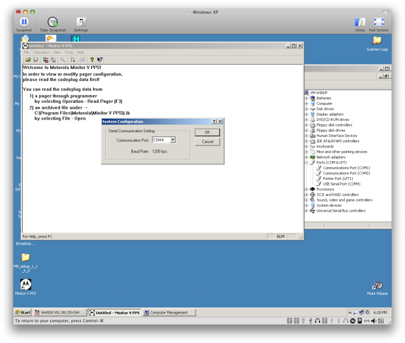
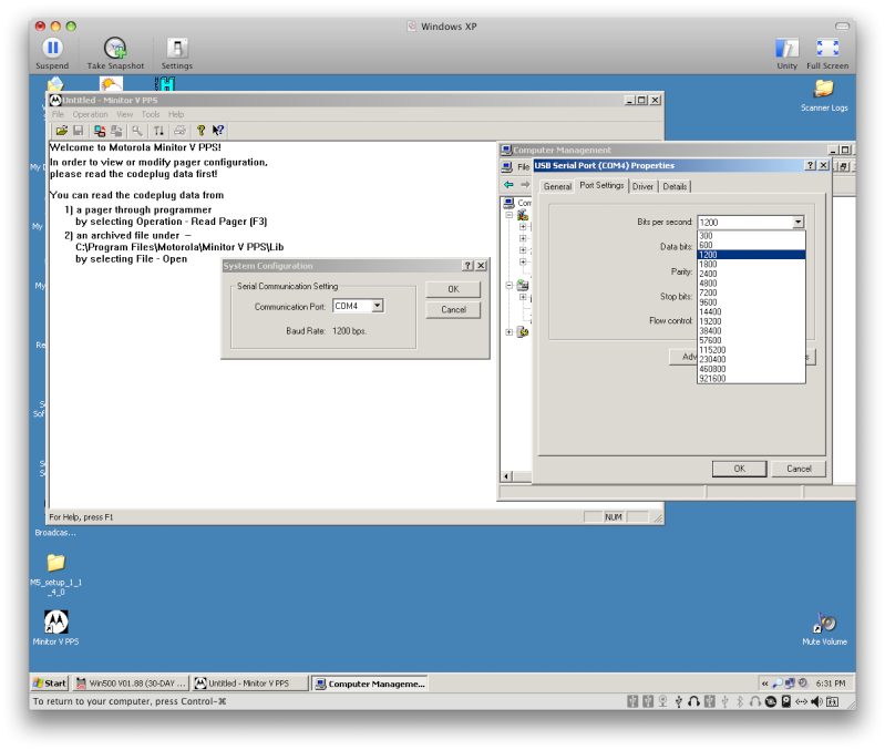
First of all, no matter which route you go, your going to need the PPS (Pager Programming Software) for the Minitor III & IV they software is sold by Motorola, since it is a paid software I will not post any links or share them here. But for the Minitor V, the software is freely downloadable from Motorola's website. You can find it here. I think the PPS is pretty self explanatory so I won't get into details on how to use that.
Now, as far as programming interface goes...
If you wish to build a complete solution for yourself you may refer to the wronderful write up already done for you at radioetcetera (Radio & Electronics Projects - Minitor Programmer) prepared by Andy Knitt.
I took alot of information from Andy's site, and decided to go a slightly different route. Not only do I prefer USB (mainly because I run macs, and can only use usb serial devices with my XP virtual machine), but I am not the best when it comes to building circuit boards.
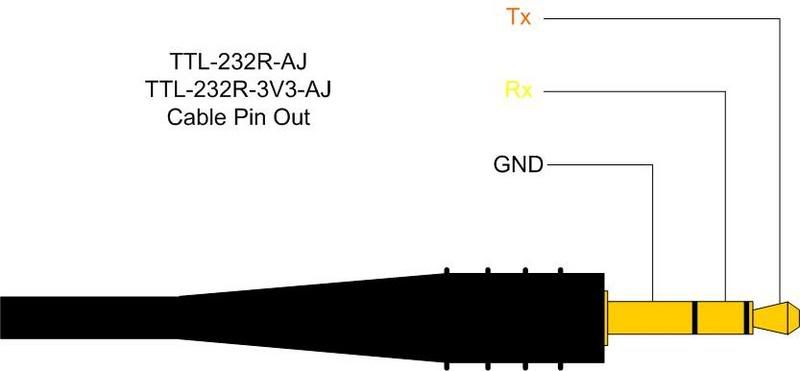
What I decided to do, was utilize the Radio Shack Scanner Programming Cable (USB Scanner Programming Cable - RadioShack.com) which I already owned. Essentially the RS 20-047 is a USB to RS232 adapter via the FTDI FT232BL chip, which is then converted to a TTL device terminated with a 1/8" stereo male TRS connector. The tip is the TTL Tx, the ring is the TTL Rx, and the sleeve is the Ground. This can also be seen in the diagram below. (Thanks to RR member Evert for the info and the diagram on the RS 20-047).
I still needed a way to connect the tip, ring and sleeve of the connector on the programming cable to the appropriate pins on the bottom connector of the Minitor pager (more on the different pinouts below). I did this early on as some may have seen from the images in the Minitor thread by just using alligator clips and some copper pins, but I wanted something slightly easier.
I decided to build a very cheap and very homemade programming dock for my Minitor V. The pinouts are different on the III/IV than the V, so if you need both you would need to build two boxes or something similar to support the different pin configurations.
I went to my local hobby electronics store and purchased a small project enclosure, a 1/8" stereo TRS jack, some wire, and dug through a box of random connectors and plugs to find something with copper pins that seemed to fit well in the pins on the bottom of the Minitor. All and all I spent less than $10 after tax on the supplies to build.
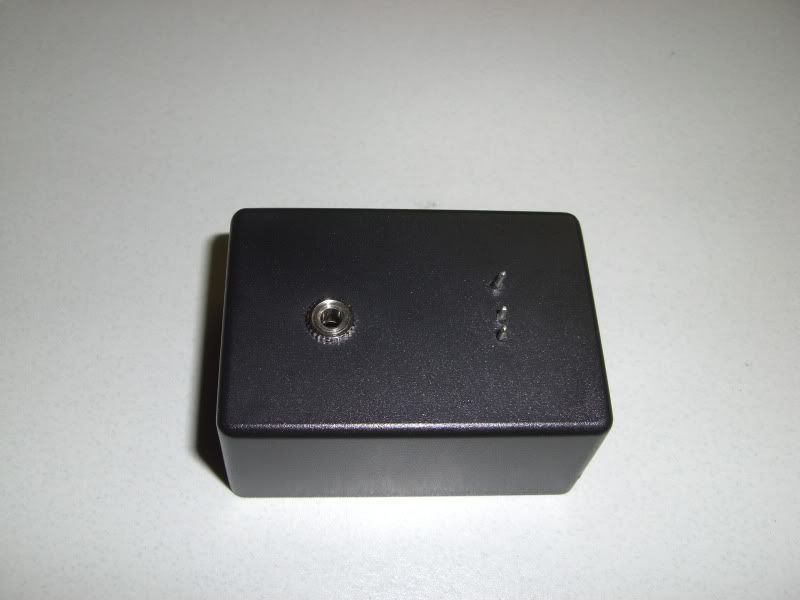
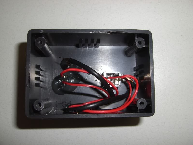
At that point all the needed to be done was solder wires from the ring, tip and sleeve of the jack to the copper pins, and mount everything in the project box. I drilled small holes for the copper pins in the project box so that they would align with the correct connectors on the bottom of the Minitor and held them in place with hot glue from the inside, then drilled a 1/8" hole to mount the TRS jack. Ensured all the connections were working using the continuity tester on my multimeter and closed it all up.
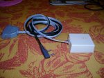
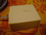
Here are some images of my homemade programming dock.
Now when I want to program my Minitor, I simply plug in my RS Scanner Programming Cable into the programming dock and set my Minitor into programming mode (set select knob to "C" and turn Minitor on while holding the reset button on the side) and set it in to the dock making sure the connectors go in the right place and then I can read and write codeplugs til my heart is content.
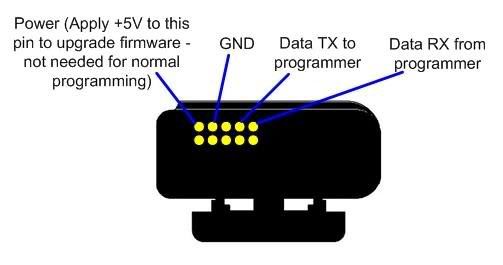
I should note, that I did not setup my programmer to provide power to the pager during programming, as (at least for the V) this is only required for upgrading the firmware, and I had no intentions of doing so.
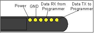
Diagrams for the pinouts of the Minitors III, IV and V can be found below, again, these are pretty self explanatory.
Minitor III/IV
Minitor V:
Well if you made it this far, you have stuck with my terrible write up skills and now know how to program your Minitor pager on the cheap. If you have any questions please post them in this thread and I will do my best to assist you.
Again, thank you to Andy at radioetcetera for all the valuable information I got from his site, as well as letting me use his diagrams, and thank you to Evert here at RR who gave me the pinout to the RS 20-047 programming cable so that I could manage to do this.
Hopefully at least someone can now program their Minitor, and not have to fret over spending several hundreds of dollars on the necessary equipment.
I have had several requests for me to actually write something up on this for people here at RR that wish to program their Minitor III, IV, and V pager without having to drop hundreds on the Motorola programming cable and programming dock. So here goes.
First of all, no matter which route you go, your going to need the PPS (Pager Programming Software) for the Minitor III & IV they software is sold by Motorola, since it is a paid software I will not post any links or share them here. But for the Minitor V, the software is freely downloadable from Motorola's website. You can find it here. I think the PPS is pretty self explanatory so I won't get into details on how to use that.
Now, as far as programming interface goes...
If you wish to build a complete solution for yourself you may refer to the wronderful write up already done for you at radioetcetera (Radio & Electronics Projects - Minitor Programmer) prepared by Andy Knitt.
I took alot of information from Andy's site, and decided to go a slightly different route. Not only do I prefer USB (mainly because I run macs, and can only use usb serial devices with my XP virtual machine), but I am not the best when it comes to building circuit boards.
What I decided to do, was utilize the Radio Shack Scanner Programming Cable (USB Scanner Programming Cable - RadioShack.com) which I already owned. Essentially the RS 20-047 is a USB to RS232 adapter via the FTDI FT232BL chip, which is then converted to a TTL device terminated with a 1/8" stereo male TRS connector. The tip is the TTL Tx, the ring is the TTL Rx, and the sleeve is the Ground. This can also be seen in the diagram below. (Thanks to RR member Evert for the info and the diagram on the RS 20-047).

I still needed a way to connect the tip, ring and sleeve of the connector on the programming cable to the appropriate pins on the bottom connector of the Minitor pager (more on the different pinouts below). I did this early on as some may have seen from the images in the Minitor thread by just using alligator clips and some copper pins, but I wanted something slightly easier.
I decided to build a very cheap and very homemade programming dock for my Minitor V. The pinouts are different on the III/IV than the V, so if you need both you would need to build two boxes or something similar to support the different pin configurations.
I went to my local hobby electronics store and purchased a small project enclosure, a 1/8" stereo TRS jack, some wire, and dug through a box of random connectors and plugs to find something with copper pins that seemed to fit well in the pins on the bottom of the Minitor. All and all I spent less than $10 after tax on the supplies to build.
At that point all the needed to be done was solder wires from the ring, tip and sleeve of the jack to the copper pins, and mount everything in the project box. I drilled small holes for the copper pins in the project box so that they would align with the correct connectors on the bottom of the Minitor and held them in place with hot glue from the inside, then drilled a 1/8" hole to mount the TRS jack. Ensured all the connections were working using the continuity tester on my multimeter and closed it all up.
Here are some images of my homemade programming dock.


Now when I want to program my Minitor, I simply plug in my RS Scanner Programming Cable into the programming dock and set my Minitor into programming mode (set select knob to "C" and turn Minitor on while holding the reset button on the side) and set it in to the dock making sure the connectors go in the right place and then I can read and write codeplugs til my heart is content.
I should note, that I did not setup my programmer to provide power to the pager during programming, as (at least for the V) this is only required for upgrading the firmware, and I had no intentions of doing so.
Diagrams for the pinouts of the Minitors III, IV and V can be found below, again, these are pretty self explanatory.
Minitor III/IV

Minitor V:

Well if you made it this far, you have stuck with my terrible write up skills and now know how to program your Minitor pager on the cheap. If you have any questions please post them in this thread and I will do my best to assist you.
Again, thank you to Andy at radioetcetera for all the valuable information I got from his site, as well as letting me use his diagrams, and thank you to Evert here at RR who gave me the pinout to the RS 20-047 programming cable so that I could manage to do this.
Hopefully at least someone can now program their Minitor, and not have to fret over spending several hundreds of dollars on the necessary equipment.


