Question about LNA, FM trap and attenuator

Status
Not open for further replies.

TGuelker

Retired ASE CMAT L1 MRRT
Premium Subscriber
Joined
Dec 17, 2021
Messages
392
Location
Collinsville, Illinois
Currently my setup is Diamond discone -> LMR400UF -> MiniCircuits LNA (in the house) -> MiniCircuits FM notch filter -> variable attenuator -> SDS200

I realize the LNA should be at the antenna, but since I am using LMR400UF, the loss is negligible to me.

Should the attenuator be placed before the filter or after?

Thanks
 

ArloG

Member
Joined
Feb 14, 2020
Messages
367
I'll jump in. I don't know the model of your MiniCircuits LNA.
But any amplifier if it doesn't have AGC will saturate out of its linear region if given more signal than it's designed for.
I believe that's why many mast mount preamps have a variable gain control. Then again. Receivers have gain controls after the RF amp.
Switchable attenuators before the RF amp are common also.
Just grabbing a data sheet for one of the MiniCircuits wideband connected LNA's with SMA connectors gives maximum specs of +19dBm for 5 minutes and +16 dBm continuous.
So if there is a chance of saturating the input and risking over driving it. An attenuator before it would make perfect sense.
 

prcguy

Member
Premium Subscriber
Joined
Jun 30, 2006
Messages
17,122
Location
So Cal - Richardson, TX - Tewksbury, MA
I'll jump in. I don't know the model of your MiniCircuits LNA.
But any amplifier if it doesn't have AGC will saturate out of its linear region if given more signal than it's designed for.
I believe that's why many mast mount preamps have a variable gain control. Then again. Receivers have gain controls after the RF amp.
Switchable attenuators before the RF amp are common also.
Just grabbing a data sheet for one of the MiniCircuits wideband connected LNA's with SMA connectors gives maximum specs of +19dBm for 5 minutes and +16 dBm continuous.
So if there is a chance of saturating the input and risking over driving it. An attenuator before it would make perfect sense.
He is nowhere near driving his LNA to 16 or 19dBm output levels, IMD will set in and start raising the noise floor and creating ghost signals well before the 1dB compression point and probably 40-50dB below it. You also never place an attenuator in front of an LNA, it immediately adds to the noise figure and degrades reception. Any variable LNA will have a variable gain stage or attenuation after the first LNA section.

If you were to start with an LNA that had .5dB noise figure and 25dB gain that was being pushed into IMD land then you placed a 10dB attenuator in front of the LNA you would now have a 10.5dB noise figure 15dB gain LNA and reception would suck. The proper fix is a higher IP1/IP3 LNA with less gain.
 

ArloG

Member
Joined
Feb 14, 2020
Messages
367
He is nowhere near driving his LNA to 16 or 19dBm output levels, IMD will set in and start raising the noise floor and creating ghost signals well before the 1dB compression point and probably 40-50dB below it. You also never place an attenuator in front of an LNA, it immediately adds to the noise figure and degrades reception. Any variable LNA will have a variable gain stage or attenuation after the first LNA section.

If you were to start with an LNA that had .5dB noise figure and 25dB gain that was being pushed into IMD land then you placed a 10dB attenuator in front of the LNA you would now have a 10.5dB noise figure 15dB gain LNA and reception would suck. The proper fix is a higher IP1/IP3 LNA with less gain.
I appreciate the theory and math involved. Perhaps I was misleading on where to place an attenuator. It was suggested by a quick Google and then something sparked my memory.
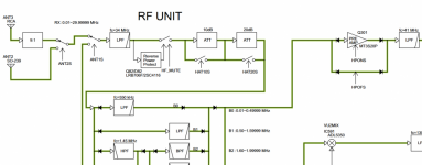
Do you thing Icom and possibly others are doing it all wrong? With Q301 being the switchable preamp showing the bypass rail.
1682528936481.png
 

prcguy

Member
Premium Subscriber
Joined
Jun 30, 2006
Messages
17,122
Location
So Cal - Richardson, TX - Tewksbury, MA
I appreciate the theory and math involved. Perhaps I was misleading on where to place an attenuator. It was suggested by a quick Google and then something sparked my memory.
Do you thing Icom and possibly others are doing it all wrong? With Q301 being the switchable preamp showing the bypass rail.
View attachment 140800
In an HF receiver its not uncommon to place an attenuator in front of an LNA or bypass the LNA because its a much different SNR situation and many HF receivers have a lousy front end or first mixer that overloads easily and its a cheap fix. For VHF and above noise figure is a prime concern and different methods would be used to reduce gain in the receiver. A VHF/UHF antenna system is different still and should be designed to play nice under any conditions it might encounter without needing any interaction. You want the antenna system including any LNAs or filters to do its job well, not cause any problems and be something you don't have to think about.

I would think adding an LNA in the OPs basic system would cause more problems than good unless the LNA is a very high level unit with low noise figure and low gain like 10dB or less. The only advantage it would have is if the LNA noise figure is noticeably better than the receiver noise figure, but even an SDS200 will have some front end filtering to help it survive where I don't see any mention of filters in front of the OPs LNA. That takes a great LNA and/or an area with no high level RF to cause problems.
 
Last edited:

Ubbe

Member
Joined
Sep 8, 2006
Messages
10,008
Location
Stockholm, Sweden
SDS100 and SDS200 doesn't play well with LNA's as they already use a preamplifier where its gain have been experimented with to find the optimum value for the majority of users. Its SDR receiver can't handle big signals and are already at the level of being overloaded.

What can help with a LNA are to reduce the noise level by just having a total gain of 3-4dB. Antennas for scanners usually have a very varying impedance over it's working frequency range. It will help to use the LNA at the antenna to produce an almost constant 50 ohm to the coax. The bandfilters in the scanner also have varying impedance depending of the received frequency and using an isolating splitter will also give an almost constant impedance to the coax and will an attenuation that needs a LNA to compensate for the loss.

Scanners usually are more prone to overload the lower in frequency it goes and can tolerate bigger signals the higher in frequency it goes. The LNA should then have a slope that gives more gain at higher frequencies and will also compensate for a coax higher attenuation at higher frequencies. A small capacitor in series inside the splitter or at the LNA's output can take care of that if the LNA doesn't have any EQ.

Placing any external filter after an LNA will have no impact on the signal but placing it before the LNA will drop the signal level sligthly as there's never a 0dB inline attenuation thru it, but then the LNA needs to cope with big signals that might raise its noise level and its capability to handle IM. It has to be experimented and tested where the filter makes the most use as it depends of the antenna type and what transmitters that are local and how close they are.

/Ubbe
 

ArloG

Member
Joined
Feb 14, 2020
Messages
367
To be honest I felt like pcrguy was yelling at me at me.
It made me wonder how a passive device could add to noise. Considering the whole concept of low noise amplifiers are large gain with minimal atomic noise.
Thinking back to the LNA's on c band tvro dishes from the 80's with separate detatched downconverters.
When gasfet's, etc. were hand picked and sorted for their low noise, kelvin temperature.
An interesting conversation with what seems to make valid points. All the math aside. Is linked here below.
Makes me think that a wideband antenna with overwhelming RF undesired frequencies (FM broadcast) would benefit from attenuation before the preamp section. Definitely notching the undesired would be beneficial. It seems to me.

In the IC-R8600 diagram ANT2S is the switched N Type connector for 30-3000 MHz antenna input. Pre filtering and pre attenuation.
But all before the switchable LNA.


I guess I'm more understanding of audio circuitry. But certainly enjoy RF also. In the case of CD, DVD, Digital input sources.
They output a 2 V peak to peak signal. And receivers with inputs for them are specified to accept the higher levels.
If you were to attach the same players to a tape in, aux. port. Sound levels are much higher and distortion is most likely going to happen in the preamplifier section. But inline attenuators designed for the purpose of knocking the level down certainly do not create noise.
The circuitry of them most probably being a voltage divider.

Where am I missing that a passive component attenuator could add to noise figures?


prcguy

Member
Premium Subscriber
Joined
Jun 30, 2006
Messages
17,122
Location
So Cal - Richardson, TX - Tewksbury, MA
I'm not yelling, even though it may feel like it.

If you look at a noise figure calculator or spread sheet for calculating noise figure it can have places for one or several LNAs cascaded and attenuation before, in between or after each LNA. I don't have a NF calculator handy but in all cases the first LNA and any attenuation in front of it adds directly to the total noise figure. For example a 20dB gain amplifier with .5dB noise figure as the only thing in the chain will have the exact same gain and noise figure in the calculation. Adding a second LNA with the same specs after the first will only contribute a very small amount to the total noise figure, maybe .05dB and the gain will be the total of the two amps combined.

Add any attenuation in front of the first LNA and it adds directly to the total noise figure, so a .5dB noise figure, 20dB gain amplifier with a 3dB attenuator in front of it will result in a total noise figure of 3.5dB and a gain of 17dB. A 10dB attenuator in front of the same LNA will now be 10.5dB noise figure and 10dB gain. Add a second LNA after the first that is .5dB noise figure and 20dB gain and with no attenuation anywhere, for both LNAs in series the total noise figure will be very slightly worse, maybe .505dB noise figure and 40dB of gain. Add 10dB attenuation in front of the first LNA and now you have 10.505dB noise figure, 30dB gain and so on.

Adding attenuation after the first LNA preserves the noise figure of the amplifier for the most part and can tailor the gain for the best fit to the receiver, with some caveats. If the first LNA has just too much gain like using a 30dB job to feed a single receiver, that extra unnecessary gain can cause the amplifier to be pushed into IMD land or overload prematurely compared to a similar LNA with less gain like 10 or 15dB. Its usually unnecessary to have more than about 10dB of gain feeding a receiver unless you need more gain to make up for feedline loss after the LNA or to make up for power divider loss, etc, all after the LNA. Any more gain than that will usually cause problems.

The final piece of the pie is eliminating any loss between the antenna and first LNA and if adding any filtering in front of the LNA to mitigate strong out of band signals being careful to balance the frequency, bandwidth, skirts and insertion loss of that filter to reduce interference while maintaining the lowest noise figure.
 

Ubbe

Member
Joined
Sep 8, 2006
Messages
10,008
Location
Stockholm, Sweden
It might be easier to think that if the receiver have a sensitivity of -120dBm with some noise in it, if you then attenuate the signal then there are no signal left and its only noise. The more you attenuate a signal the more noise you get. If you receive a -80dBm signal then adding a 10dB noise level doesn't matter, it's only at the weakest signal levels that the noise level becomes important.

If you have a filter before an amplifier then if the filter attenuates 2dB of a low signal then it might disappear in the noise and when its gone it can never be recovered by an amplifier. I have only low signal levels at my place so I always have filters after the LNA to get the most signal from the antenna.

/Ubbe
 

TGuelker

Retired ASE CMAT L1 MRRT
Premium Subscriber
Joined
Dec 17, 2021
Messages
392
Location
Collinsville, Illinois
I feel like Sad Sack listening in on a phd lecture.

From what I discerned LNA -> FM filter -> attenuator is recommended.

Thanks to all. Still waiting to get on the roof one last time to rotate my coax.
 

ArloG

Member
Joined
Feb 14, 2020
Messages
367
Got it. I think. Had to twist my brain around. And apologies to Fixitt, didn't mean to hijack the post.
So an LNA or any amplifier for that fact has inherent noise. From electron flow, etc.
Short the input to it and the noise of the amp is still there. Got that.
But notching, low pass, high pass filtering out strong undesirable freqs. before the antenna is a good think right?
That would hopefully kill harmonics of strong FM broadcast signals (for example) that would show up throughout tuning if they were strong enough?

Just brings back something I did a long time ago. Cascading two mast mount Channel Master TV antenna boosters.
The intention was to bring in weak FM radio from a city 100 miles or so away. Buffalo to be specific.
It did work pretty good. But stereo was full of 19 kHz hiss. So mono FM was the only way to kill the pilot. It wasn't static for the most part.
TV stations came in a lot better. And I know the golden rule. No signal, no chance amplifying what isn't there. Like the cell phone boosters people buy when the live in the sticks in a valley and no towers close by.

Just one other thing. Icom referred me to a former tech in Georgia when I asked if they knew of anyone out there who could align my IC-R8500 after they stopped supporting them. I contacted him. Nice guy.
I had all of the test equipment to perform the step by step alignment except for a service monitor/sig. gen.
Mine only went to 1 GHz. Needed to go to 2 GHz.
He mentioned something about I could use it but I'd have to use a 2 gigahertz harmonic with 7 dB attenuation factored in.
I sent it to him. Did a real nice job. Still works great today.
In the interim. I fed the receiver a 1 GHz modulated signal. But with the radio tuned to 2 Ghz, got nothing at all.
 
Status
Not open for further replies.
Top