BCD325P2/BCD996P2: RH96 on a BCD996P2? Yep!

Status
Not open for further replies.

joesheets

Member
Joined
Jan 10, 2009
Messages
227
Location
Sandhills, NC
OK. I just checked the first board that I I used and could not program. I took all of the leads off of it to place them on a new board.
When I tried to upload the 996 to it. it worked with no issue. So it has to be the wiring.
Here is the USB board wiring form the instructions I have...USB Board.PNG
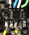
Clearly differnt than what you have
 

milcom_chaser

Member
Joined
Jul 4, 2010
Messages
980
Just for clarity, the photo on the left is from the instructions, the one on the right is a zoom in of what you posted. Should be pads 2,3,5HIS.pngYOURS.png
 
Last edited:

milcom_chaser

Member
Joined
Jul 4, 2010
Messages
980
Assuming the pads from left to right are 1,2,3,4,5. I don't have a pin-out drawing of that board...
 

joesheets

Member
Joined
Jan 10, 2009
Messages
227
Location
Sandhills, NC
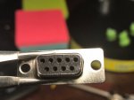
actually the pics and schematic is correct. Look at this pic where I laid the removed connector from the board as per the instructions.
# 5 in this case would be on the R (looking from the backside instead of head on). So from R to L from above, it would be 5, 4, 3, 2, 1

IMG_2128.jpg
 

milcom_chaser

Member
Joined
Jul 4, 2010
Messages
980
actually the pics and schematic is correct. Look at this pic where I laid the removed connector from the board as per the instructions.
# 5 in this case would be on the R (looking from the backside instead of head on). So from R to L from above, it would be 5, 4, 3, 2, 1

View attachment 72509
Good catch with the connector orientation. So, is it working now?
 

milcom_chaser

Member
Joined
Jul 4, 2010
Messages
980
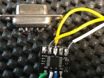
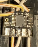
Look at the upper left of this photo. Looks like a solder bridge? That may pull the TTL voltage of that data pin to 0vdc...solder bridge.pngsolder bridge.png
 
Last edited:

joesheets

Member
Joined
Jan 10, 2009
Messages
227
Location
Sandhills, NC
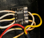
A bit of progress...maybe.. I programmed a new board successfully and then mounted the wires to it. I hooked it up to my 996 and the RH96 still says "Scanner Unconnected". On the board, the PWR light is on and the RX light is flickering. It goes off when I turn the scanner off so I assume that the Nano is receiving the scanner signal, it just isn't relaying it to the RH96. Any ideas as to why this would happen?
 

joesheets

Member
Joined
Jan 10, 2009
Messages
227
Location
Sandhills, NC
Could I have wired the audio jack backwards? I could not determine which terminal was Transmit and which one was Receive. Would that make a difference? They were labeled 2 & 3, not T & R.
 

milcom_chaser

Member
Joined
Jul 4, 2010
Messages
980
Try reversing the wires to solder pads 2 and 3 on RS-232 board. So, swapping TX and RX data. Or swap them at the audio jack connector if that's easier.
 

AKJohnny

Scanner Addict
Premium Subscriber
Joined
Jan 18, 2007
Messages
140
Location
Kendall County, IL
A bit of progress...maybe.. I programmed a new board successfully and then mounted the wires to it. I hooked it up to my 996 and the RH96 still says "Scanner Unconnected". On the board, the PWR light is on and the RX light is flickering. It goes off when I turn the scanner off so I assume that the Nano is receiving the scanner signal, it just isn't relaying it to the RH96. Any ideas as to why this would happen?
On the BCD996P2 make sure you set the GPS Baud Rate to 9600 in the Menu>Settings>Set GPS Baudrate menu item.
 
Status
Not open for further replies.
Top