kf4lne
Member
Right, no other element has any electrical connection to it.


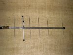
") . drill 2 holes behind the reflector for a 'U' clamp to a mast, or a hole in each end to hang with string in the attic.
. drill 2 holes behind the reflector for a 'U' clamp to a mast, or a hole in each end to hang with string in the attic.trainman111 said:I have built a 3 element yagi tuned to 161.000 Mhz. using instructions from http://www.alabamarailfan.com/scanner.php. The directions didn't say anything about having to cut the driven element in half. It did say however that it does look like an electrical short-circuit
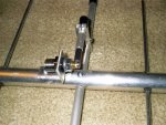
TeRayCodA said:The gamma match I made is from a SO-239 antenna "feedthrough" connector,drilled/tapped for a 8/32 S/S screw,to attach the gamma rod.
I would suggest using a " N" type connector instead,if I had to do it over again.That is what I had handy at the time.But,it still works great.
The driven element is 1/2" aluminum tubing,the shorting strap is made from some scrap aluminum.I bought most everything at Lowe's for this project.