Homebrew Remotehead for DMA Uniden

Status
Not open for further replies.

richk107

Member
Joined
Apr 23, 2009
Messages
90
Location
New Jersey
I took a look at the Arduino example sketch and threw something together pretty quick. It looks like it won't be too hard to implement. I'll play around with it tonight and post something for people to try if it works. The biggest problem I see is that not all radios have the same volume scale. the 396XT volume goes from 0 to 15 while the 996T is from 0 to 29. Nice round numbers. I already have a variable people are to change depending on which model of scanner is being used. As long as that is set properly the code for a pot should work fine.

Rich
 

richk107

Member
Joined
Apr 23, 2009
Messages
90
Location
New Jersey
So that wasn't so bad. We are now at Version 2.3.1

You can now control the scanner using a trim pot OR buttons, but not both. There is a variable that must be set depending on your configuration which determines which method you would like to use. Set volSource to 0 if you would like to use buttons or 1 if you want to use a trim pot.

//======= Scanner specific information - set values appropriate for your configuration ========
int maxVolume = 15; // maximum volume for scanner. 396XT goes to 15, 996T goes to 29.
int lcdRows = 4; // only 2 and 4 lines LCDs supported
int volSource = 1; // set value to 0 for button or 1 for trim pot.

I made it easier for everyone by placing the user defined variables in one location. Set you maximum volume for your scanner, which type of LCD display you are using and how you wish to control the volume. To determine your max volume, use your scanner volume knob and see what number is displayed on the scanners LCD.

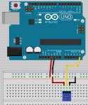
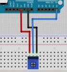
I used a 10K pot similar to the one found on SparkFun https://www.sparkfun.com/products/9806 Three wires are needed, one leg goes to 5V, center goes to Analog 5, remaining leg goes to Ground. Check attached pic.
 

Attachments

  • UnidenHomebrewVolumePot.JPG
    UnidenHomebrewVolumePot.JPG
    60.1 KB · Views: 1,343
  • HomebrewRemoteforUniden_v2_3_1.zip
    4.5 KB · Views: 109

mancow

Member
Database Admin
Joined
Feb 19, 2003
Messages
6,907
Location
N.E. Kansas
Not to nit pick but just in case someone is following the illustration the black wire should be up on the top row in line with the other one. As it is there it's shorted to + voltage. It's a good idea to use the REF voltage instead of raw 5v since it's a source meant exactly for these applications.
 

richk107

Member
Joined
Apr 23, 2009
Messages
90
Location
New Jersey
The image has been corrected. Thanks for the catch.

As for using AREF with the pot, I've never used it that way. I took a quick look around and I couldn't find any tutorials. The way I've always used a potentiometer and every tutorial I've seen uses 5 or 3.3V and an analog pin.

If you have another way, please share as I'd like to take a look at it.


Rich
 

Attachments

  • unidenHomebewpotPot.JPG
    unidenHomebewpotPot.JPG
    46.1 KB · Views: 1,245

richk107

Member
Joined
Apr 23, 2009
Messages
90
Location
New Jersey
The post containing the source is on this page, a couple replies up. The post was made on 09-04-2013, 3:03 PM

Rich
 

MDM38

Member
Joined
Oct 23, 2011
Messages
22
I had to put this project aside for a bit but here is what I have complete so far. I unfortunately had to send the scanner to Uniden for repairs after trying to move the bnc connection to the side of the case unsuccessfully.

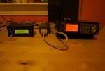
The first picture shows the BCT15, the Arduino and the remote display.

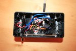
The second picture shows the inside of the remote display.

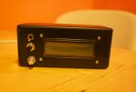
The third picture shows the front of the remote display. The top switch is an on/off switch for the power to the remote display, Arduino and BCT15. The middle is a momentary push button that controls scan/hold. The bottom is a pot that adjusts the volume.

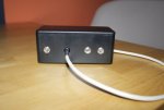
The fourth picture shows the rear of the remote display. The left barrel jack is for the 5v power that comes from the Arduino. The cord coming out is a serial cable that connects to the Arduino. The middle barrel jack is for 12v out to power the Arduino and BCT15. The right barrel jack is for 12v in, coming from the power source.

More pictures in the following post.
 

Attachments

  • IMG_4705s.jpg
    IMG_4705s.jpg
    97.8 KB · Views: 951
  • IMG_4707s.jpg
    IMG_4707s.jpg
    134.2 KB · Views: 937
  • IMG_4709s.jpg
    IMG_4709s.jpg
    84.1 KB · Views: 932
  • IMG_4714s.jpg
    IMG_4714s.jpg
    80.4 KB · Views: 943

MDM38

Member
Joined
Oct 23, 2011
Messages
22
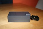
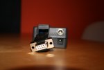
The first picture shows the Arduino's case.

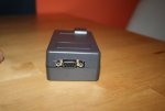
The second picture shows the side of the Arduino's case which has a serial connection that the BCT15 is connected to.

The third picture shows the other side of the Arduino's case which has a serial connection that goes to the remote display. The barrel jack on the top is for 5v power from the Arduino to the remote display. The barrel jack on the bottom is for 12v power in to power the Arduino and the rs232-to-ttl converter.

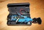
The fourth picture shows the inside of the Arduino case.


Richk107 - To answer your question about powering the rs232-to-ttl chip with power from the Arduino vs a separate usb source, I believe the issue was resolved with the software version 2.3 because I am no longer able to reproduce the problem. The converter I am using has an SP3232 chip.


I would like to thank everyone who contributed to this board for your help on this project, especially Xeno194 and Richk107.

I will keep you all posted on any future progress once I hopefully get my repaired BCT15 back.
 

Attachments

  • IMG_4716s.jpg
    IMG_4716s.jpg
    83.3 KB · Views: 954
  • IMG_4717s.jpg
    IMG_4717s.jpg
    82.3 KB · Views: 941
  • IMG_4718s.jpg
    IMG_4718s.jpg
    73.7 KB · Views: 942
  • IMG_4719s.jpg
    IMG_4719s.jpg
    125.3 KB · Views: 1,005

richk107

Member
Joined
Apr 23, 2009
Messages
90
Location
New Jersey
Fantastic. I was thinking of splitting the equipment between two enclosures as well to reduce the size of the LCD.

Great Job

Rich
 
Status
Not open for further replies.
Top