Homebrew Remotehead for DMA Uniden

Status
Not open for further replies.

mibzzer15

Member
Joined
Apr 14, 2009
Messages
394
Location
Fremont, CA
Ok....well i cant help out too much with development of the software and hardware....but like i said....I could help test out anything and give feedback. I really wish I knew how to actually program the hardware or code the software :/
 

richk107

Member
Joined
Apr 23, 2009
Messages
90
Location
New Jersey
Looks good. The code from VB is different then what gets uploaded to an Arduino. The Arduino is more like C++, C# or Java. You'll have to do some translation between the two to get it running.

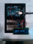
Below is my Arduino setup for the project. I only have four buttons as I plan to condense the volume controls to just volume up/down. The other two will be scan and hold.

I've also attached a picture of a program I was working on that stalled due to other commitments. Similar to yours (you have a better layout) with the exception of the two frequency buttons. These are hardcoded frequencies. My plan was to utilize them for instant access to a specific frequency.

Rich

Software is almost done. I named it uniden commander but now i have to change it because that names is being used. here is a sneak peek. I will most likely get the software done before the hardware because i ordered parts from all over china. They are coming in the mail little by little so i will be working on the software in the meantime. Anybody want to work on the software with me? let me know (visual basic express 2010 its free)
 

Attachments

  • IMG00370-20110524-1518.jpg
    IMG00370-20110524-1518.jpg
    58.4 KB · Views: 1,797
  • form.jpg
    form.jpg
    24.5 KB · Views: 1,774

Stupidfatkid

Member
Joined
Apr 26, 2004
Messages
171
Location
Kansas
Ordered my Arduino parts today. I've been wanting to do something like this for awhile, just needed some motivation. If you want any help with your software let me know. I know just enough to be dangerous. I wrote a virtual display in VB for the 780 several years ago.

Uniden BC780XLT Virtual Display Version II


Software is almost done. I named it uniden commander but now i have to change it because that names is being used. here is a sneak peek. I will most likely get the software done before the hardware because i ordered parts from all over china. They are coming in the mail little by little so i will be working on the software in the meantime. Anybody want to work on the software with me? let me know (visual basic express 2010 its free)
 

SCPD

QRT
Joined
Feb 24, 2001
Messages
0
Location
Virginia
Im glad i got a few people here onboard with this project. Stupidfatkid I would really like to teamup and work on the software end of this with you. Can you download visual basic express 2010 we can email the project back and forth and than post it on here when its done. I dont know if i want it open source but it will be a freeware app. Let me know I will start to redesign the frontend.
 

K4APR

Member
Joined
Apr 18, 2003
Messages
1,028
Location
Chesapeake, VA.
I am actually a PIC C guy myself, so I prefer to just write all of the code from start. However, I do have some Arduinos of several flavors in my shop. Including one called a Netduino. The nice feature of this is that it can be programmed through Microsoft's free Visual C# Express environment. I am not sure how portable the code is, but if you develop your Win32 app in C#, you might be able to re-use most of the code on a Netduino based hardware solution.

Just an idea!
 

SCPD

QRT
Joined
Feb 24, 2001
Messages
0
Location
Virginia
Alpha version of DMA Viewer was just posted in a new thread in the uniden section. I would really like some feedback on what os you used and what radio and if the buttons i did program worked with your radio
 

l8f57

Member
Joined
May 17, 2011
Messages
2
Software LED Control

If you have an extra PWM pin out, you should be able to control the LED brightness through software instead of a POT. This would also likely consume a pair of inputs as well.
 

Stupidfatkid

Member
Joined
Apr 26, 2004
Messages
171
Location
Kansas
Any recent progress on the Arduino project? I just received my Arduino and LCD in the mail.


Alpha version of DMA Viewer was just posted in a new thread in the uniden section. I would really like some feedback on what os you used and what radio and if the buttons i did program worked with your radio
 

SCPD

QRT
Joined
Feb 24, 2001
Messages
0
Location
Virginia
I have been working on for the past 3 days :) I will post what i have tomorrow in the afternoon. I finished the uniden button commander app and scrapped the realtime data display in the app.
 

Stupidfatkid

Member
Joined
Apr 26, 2004
Messages
171
Location
Kansas
I bought a couple XBee wireless modules too. Once I get the Arduino talking to the 996 and the LCD I thought it would be cool to add in the XBee modules and make the head wireless. At this point the wireless idea is putting the cart before the horse but it would be cool to eventually get there.

Hopefully I'll have some time to start working on it this weekend.

I have been working on for the past 3 days :) I will post what i have tomorrow in the afternoon. I finished the uniden button commander app and scrapped the realtime data display in the app.
 

SCPD

QRT
Joined
Feb 24, 2001
Messages
0
Location
Virginia
I was actually going to go one up on the xbee and use serial to bluetooth and vise versa.
 

SCPD

QRT
Joined
Feb 24, 2001
Messages
0
Location
Virginia
Here is my button assembly

Parts are:

RS PCB
Multipurpose PC Board with 417 Holes - RadioShack.com

6-10k resistors 1 for each button
100 pcs 10k ohm 1/4W, 5% carbon film resistors. | eBay

1 ground to common ground bus going to arduino ground

6 4pin PCB pushbuttons
30 pcs Mini Push Button Switches For Electronic DIY - eBay (item 110627441829 end time Jun-20-11 06:16:46 PDT)

Here is a blank board if you want to copy my design
View attachment 32753

View attachment 32751
View attachment 32752

Buttons will goto arduino digital pins
13
12
11
10
9
8

Than send the commands for my radios (346xt & bc15x)
Volume High
Volume Low
Mute
Scan
Scan Up
Scan Down

Don't know if im going with the LCD yet cause i had a lot of problems when i did a software version of this.

Mike
 
Last edited:

Stupidfatkid

Member
Joined
Apr 26, 2004
Messages
171
Location
Kansas
I don't know if this helps you with your LCD issue, but this is what I referenced when I wrote the virtual display for the BC780XLT. I think the control code is the same for the 996 and 396. If you send the LCD<cr> command to the radio it will respond with a comma delimited dump of the LCD which you can then parse into an array with the VB split() function. You can also request individual elements of the LCD by referencing the list below. You've probably already been down this road but I thought I would throw it out there anyway.

LCD<cr>
returns LCD status lines as below

P - Priority indicator
E - Edaccs Trunk indicator
M - Motorola Trunk indicator
L - Ltr Trunk indicator
BANK + Bank indicator
LIST - List indicator
SCAN - Scan indicator
TRUNK - Trunk indicator
FDOT + Frequency Decimal indicator
N - N indicator used for NFM
DCS - DCS indicator
CTCSS - CTCSS indicator
AM - AM indicator
FM + FM indicator
WFM- WFM indicator
SRCH- Search indicator
HOLD + Hold indicator
FREQ - Frequency indicator
CHAN + Channel indicator
PRI - Pri indicator
DLY + Delay indicator
LOUT - Lockout indicator
ALPHA - Alpha indicator
RMT + Remote Control indicator
AUTO - Auto indicator
CDOT - Tone code decimal indicator
HZ - Hertz indicator
S + S indicator preceeding signal bars
KLOC - Key Lock indicator
ATT - Attenuator indicator
LINE - Record indicator
ALT - Alt indicator
DATA - Data indicator
BAR ----------------------------- Bar indicator for control channels
SMT +++++- Signal Meter Bars
BNK +--------* Banks Selected Status * = Currently scanning
CHN [ 2] Channel Displayed
FRQ [ 43. 7400] Frequency Displayed
CTC [ ] CTC code (Also displays the Trunk ID Code in Trunk Mode)
LINE 1 [ ][ ] LCD LINE 1 Alpha Tag
LINE 2 [Cordless Phones ][ ] LCD LINE 2 Alpha Tag

LCD label<cr>
parameter label = one of the above left listed labels. Example LCD ATT<cr>
returns "ATT -"<cr>

The - indicates the indicator is off and the + indicates it is on.

The item to the right of the label as shown in the above table will be returned plus the <cr>


Here is my button assembly

Parts are:

RS PCB
Multipurpose PC Board with 417 Holes - RadioShack.com

6-10k resistors 1 for each button
100 pcs 10k ohm 1/4W, 5% carbon film resistors. | eBay

1 ground to common ground bus going to arduino ground

6 4pin PCB pushbuttons
30 pcs Mini Push Button Switches For Electronic DIY - eBay (item 110627441829 end time Jun-20-11 06:16:46 PDT)

Here is a blank board if you want to copy my design
View attachment 32753

View attachment 32751
View attachment 32752

Buttons will goto arduino digital pins
13
12
11
10
9
8

Than send the commands for my radios (346xt & bc15x)
Volume High
Volume Low
Mute
Scan
Scan Up
Scan Down

Don't know if im going with the LCD yet cause i had a lot of problems when i did a software version of this.

Mike
 

SCPD

QRT
Joined
Feb 24, 2001
Messages
0
Location
Virginia
Stupidfatkid- I will take care of the button click events you do the lcd code. :) (For the arduino) im not going to attempt it for a while.
 

richk107

Member
Joined
Apr 23, 2009
Messages
90
Location
New Jersey
I'll take a picture of my set up later today but I wanted to just provide a list of what I'm using. I'll share some code after I finish and clean the code. I would be interested in how people code the usage of the buttons.

- Arduino Uno
- 16x2 White on Black 5V LCD
- 4 Momentary Push Button Switches
- TTL to Serial Adapter
- DB9 Null adapter

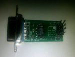
The TTL to Serial (attached pic) and DB9 Null adapter are necessary to communicate with the scanner. The Arduino does have pins labeled as serial, but the voltages and signals don't match to how we need to communicate with the scanner. It utilizes a Maxim IC MAX232 chip but there are plans that show the newer MAX3323 chip which can be built on a breadboard. The one I am using I ordered from ebay for $3 including shipping. This is connected to digital pins 0 & 1, which are the TX/RX lines and utilize the normal Serial commands. The only downside to this is that you will need to disconnect these two cables when uploading new code to the Arduino, since this will cause conflicts with the USB connection. I also played with using NewSoftSerial which can use other pins but I had issues with how the Arduino handles interrupts. When reading from the scanner the complete string would not be read from the scanner and what was read contained incorrect characters.

It’s been a fun and educational project considering I have a Computer Science degree and not one in electronics.
 

Attachments

  • IMG00430-20110607-1357.jpg
    IMG00430-20110607-1357.jpg
    33.5 KB · Views: 1,664
Status
Not open for further replies.
Top