My homemade Off Center Dipole Antenna

Status
Not open for further replies.

KC4RAF

Member
Joined
Sep 30, 2006
Messages
1,579
Location
Davenport,Fl.- home to me and the gators and the s
On your 1/2 copper pipe,

is it "L" or "M"?
"L" is heavier and tighter fit to connectors. And cost a couple of dollars more.
When I bought pipe at Lowes, they had "L" and "M" in the same rack, and I didn't check until I got home and saw the price difference, (IIRC it was about 3 bucks more for the L).
The fit was very tight and I used sandpaper to get it ready for soldering and then the flux acted like grease to fit it together.


edit: My bad. I see where you are using PVC fittings etc. Disregard my useless post.
 
Last edited:

kandrey89

Member
Feed Provider
Joined
Dec 11, 2009
Messages
320
Location
San Ramon, CA USA
I am preparing to make an OCFD myself and I did some research, perhaps unlike you? :)

3/4" copper pipe
3/4" CPVC, not PVC. CPVC has a larger inner diameter than PVC, I did some research and CPVC is 0.842" inside diameter compared to something like 0.811" for PVC, while the copper pipe is 0.875" outside diameter. While I agree that doesn't sound convincing, the wiki states it works, either way, you're not going to get any better with anything different so even if CPVC doesn't quite fit, it's better than PVC and I'll just end up sanding the copper pipe or the inside CPVC opening to get it to fit.

Copper pipe outer diameter is 1/8"+pipe listed size, so for a 3/4" it's 7/8" OD.
 

kandrey89

Member
Feed Provider
Joined
Dec 11, 2009
Messages
320
Location
San Ramon, CA USA
is it "L" or "M"?
"L" is heavier and tighter fit to connectors. And cost a couple of dollars more.

L is used for general home water application. M is drainage, non-pressure environment stuff. Either way, L and M have the same outer diameter, for 3/4" pipe, OD is 7/8". The ID is different, so it doesn't matter which type he got. copper pipe
 

kandrey89

Member
Feed Provider
Joined
Dec 11, 2009
Messages
320
Location
San Ramon, CA USA
FYI, home depot in my area, or the entire bay area in fact doesn't carry CPVC, so I have to order it online to have it delivered to the store. It's like $2 worth of parts, LOL.
 

lio_n63

Member
Premium Subscriber
Joined
Jun 18, 2013
Messages
61
Location
Central New Jersey, USA
FYI, home depot in my area, or the entire bay area in fact doesn't carry CPVC, so I have to order it online to have it delivered to the store. It's like $2 worth of parts, LOL.

So, it's 3/4" copper pipe and 3/4" CPVC pipe, T-joint, and end caps? Nothing is 1/2" diameter as it states at the beginning of this thread?
 

kandrey89

Member
Feed Provider
Joined
Dec 11, 2009
Messages
320
Location
San Ramon, CA USA
Based on his ruler and copper diameter, looks like he's using 1/2" for everything, and it works I am assuming because the ID scales for CPVC relative to copper so if it fits at 3/4" it also fits for 1/2".

I guess the OP was just careless about stating which parts and sizes he bought, CPVC vs PVC.
I'll do a better job with my thread when I get around to it ;)
 

lio_n63

Member
Premium Subscriber
Joined
Jun 18, 2013
Messages
61
Location
Central New Jersey, USA
Based on his ruler and copper diameter, looks like he's using 1/2" for everything, and it works I am assuming because the ID scales for CPVC relative to copper so if it fits at 3/4" it also fits for 1/2".

I guess the OP was just careless about stating which parts and sizes he bought, CPVC vs PVC.
I'll do a better job with my thread when I get around to it ;)

I apologize, I should've been going off of the wiki page for it. I'm going to return all of my copper pipe, pvc, and fittings and get 3/4" copper pipe and 3/4" CPVC pipe, fittings, and end caps instead. According to wiki, the CPVC fits on the copper pipe perfectly. Like you said, if the copper pipe still doesn't fit the CPVC, I'll sand something down to make it fit. I'll try the fittings at the store so I won't have to exchange it a 2nd time. I'm not going to paint it being that it will be indoors, so no need for weather proofing.

Sorry for my seemingly stupidity, like I said, I should've just gone in accordance with the wiki, not this thread's instructions. If I need to sand the copper pipe at all will it affect how the antenna works?
 
Last edited:

lio_n63

Member
Premium Subscriber
Joined
Jun 18, 2013
Messages
61
Location
Central New Jersey, USA
In addition to my last post (it won't let me edit it again), does it matter if the 48" copper pipe is 1" shorter (about 47") and the 18" copper pipe is about 1-3/4" longer (around 20")? The idiot at home depot didn't seem to want to be bothered b/c it was within the hour that they close and was struggling with the pipe cutter and that's how the mistake happened. I re-measured when I got home and noticed the error.
 

wbswetnam

Member
Premium Subscriber
Joined
Oct 11, 2005
Messages
1,808
Location
DMR-istan
The OCFD - the KF5YOF version

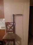
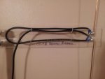
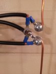
Ok so I also made an OCFD, but instead of copper pipe I used heavy copper wire, and instead of a 300 to 75 ohm TV transformer (which I couldn't find) I used a 25" section of RG8X coax to make a transmatch. She's ready for the trip up to the attic! Here are the pics:
 

Attachments

  • OCFD1.jpg
    OCFD1.jpg
    160.8 KB · Views: 962
  • OCFD coax xmatch.jpg
    OCFD coax xmatch.jpg
    161.5 KB · Views: 829
  • OCFD xmatch close-up.jpg
    OCFD xmatch close-up.jpg
    178.5 KB · Views: 944

wbswetnam

Member
Premium Subscriber
Joined
Oct 11, 2005
Messages
1,808
Location
DMR-istan
In addition to my last post (it won't let me edit it again), does it matter if the 48" copper pipe is 1" shorter (about 47") and the 18" copper pipe is about 1-3/4" longer (around 20")? The idiot at home depot didn't seem to want to be bothered b/c it was within the hour that they close and was struggling with the pipe cutter and that's how the mistake happened. I re-measured when I got home and noticed the error.

Yes, that is going to alter the SWR of the antenna. By how much, I'm not sure. You don't happen to be friends with an amateur radio operator with an SWR meter, do you?
 

wbswetnam

Member
Premium Subscriber
Joined
Oct 11, 2005
Messages
1,808
Location
DMR-istan
wbswetnam is that a broadband transmatch? Can't find a reference for it, got one?
Why not use a 4:1 Guanella BALUN? Guanella BALUN - KN9B

A broadband transmatch? No, but it works for this application. I could have purchased a 4:1 balun, yes, but I had extra RG8X coax on hand and the coaxal transmatch did the trick for bringing down the impedance to an acceptable level for a scanner.
Here's the calculator for the coax transmatch: http://www.n-lemma.com/calcs/dipole/balun.htm

I connected my SWR meter to it and here's what I got for this antenna:
154.000 Mhz: SWR is 1.6:1
159.000 MHz: SWR is 1.2:1
453.000 MHz: SWR is 1.9:1
461.000 MHz: SWR is 1.3:1
For a scanner those are very acceptable values, I think.
 

kandrey89

Member
Feed Provider
Joined
Dec 11, 2009
Messages
320
Location
San Ramon, CA USA
In addition to my last post (it won't let me edit it again), does it matter if the 48" copper pipe is 1" shorter (about 47") and the 18" copper pipe is about 1-3/4" longer (around 20")? The idiot at home depot didn't seem to want to be bothered b/c it was within the hour that they close and was struggling with the pipe cutter and that's how the mistake happened. I re-measured when I got home and noticed the error.

Can't find an article now but it illustrated for an OCFD can be thought of as collecting waves.

For example, the antenna works by absorbing a radio wave and generating a voltage across its axis.
c=299792458 m/s
Let's take a 50MHz signal, lambda = c / f
wavelength of 50MHz is 5.996 meters, let's round it up, even though speed in medium makes it even lower but whatever, 6 meters.

Imagine a single sine wave, now take the absolute value of it, meaning negative part becomes the same as positive, with a wavelength of 6 meters, superimpose it visually onto a 6 meter copper tube/wire. Now think of it as a voltage level of arbitrary amplitude.
So you've got 2 peaks, and 3 troughs. The troughs are at each end of the copper tube and in the middle at 3m mark. The peaks are at 1.5m and 4.5m marks.

You want to connect your scanner at the 1.5m or 4.5m marks in order to receive the strongest signal from that frequency from that antenna. Ignoring the effects of the scanner on the antenna.
So out of 6m you only really need 1.5m to get the 1st harmonic, what can you do? Chop off the rest of the 4.5m and call it off center fed, add another piece of a different length to be able to capture more frequencies, dipole. How do you capture other frequencies? Same method, superimpose a wave and as long as the trough does not land on the end of the antenna that's connected to the cable, you'll be able to hear it, the further away the fed point is from the harmonic peak, the worse the reception. For example for 100MHz, troughs at 0m, 1.5m and 3.0m, your fed point is at 1.5m, so you won't hear anything at 100MHz, except your second shorter piece might accommodate it.

For 75MHz, troughs are at 0m,2m,4m, peaks at 1m and 3m, so at 1.5m you'll get 70.7% reception. sin(x/4*2*pi) - Wolfram|Alpha

Maybe I'll write some software later to plot arbitrary amplitudes vs frequency to show ideal reception using an OCFD.
 

kandrey89

Member
Feed Provider
Joined
Dec 11, 2009
Messages
320
Location
San Ramon, CA USA
A broadband transmatch? No, but it works for this application. I could have purchased a 4:1 balun, yes, but I had extra RG8X coax on hand and the coaxal transmatch did the trick for bringing down the impedance to an acceptable level for a scanner.
Here's the calculator for the coax transmatch: http://www.n-lemma.com/calcs/dipole/balun.htm

I connected my SWR meter to it and here's what I got for this antenna:
154.000 Mhz: SWR is 1.6:1
159.000 MHz: SWR is 1.2:1
453.000 MHz: SWR is 1.9:1
461.000 MHz: SWR is 1.3:1
For a scanner those are very acceptable values, I think.

Right, I was going to say that config is for a specific frequency but couldn't find the reference, I had seen it before though. As long as you find it acceptable for your application.
From what I understand, the impedance mismatch is more important for transmitting than it is for receiving, though still not to be taken lightly when receiving.
 

wbswetnam

Member
Premium Subscriber
Joined
Oct 11, 2005
Messages
1,808
Location
DMR-istan
From what I understand, the impedance mismatch is more important for transmitting than it is for receiving, though still not to be taken lightly when receiving.

Exactly. Virtually any chunk of metal can be a receiver 'antenna' (I even once used a large folded-out paper clip as an antenna for my HP1 scanner when I forgot the antenna at home) but if the SWR is poor for the frequency range you are wanting to receive, your reception could be severely impaired.
 

lio_n63

Member
Premium Subscriber
Joined
Jun 18, 2013
Messages
61
Location
Central New Jersey, USA
Can't find an article now but it illustrated for an OCFD can be thought of as collecting waves.

For example, the antenna works by absorbing a radio wave and generating a voltage across its axis.
c=299792458 m/s
Let's take a 50MHz signal, lambda = c / f
wavelength of 50MHz is 5.996 meters, let's round it up, even though speed in medium makes it even lower but whatever, 6 meters.

Imagine a single sine wave, now take the absolute value of it, meaning negative part becomes the same as positive, with a wavelength of 6 meters, superimpose it visually onto a 6 meter copper tube/wire. Now think of it as a voltage level of arbitrary amplitude.
So you've got 2 peaks, and 3 troughs. The troughs are at each end of the copper tube and in the middle at 3m mark. The peaks are at 1.5m and 4.5m marks.

You want to connect your scanner at the 1.5m or 4.5m marks in order to receive the strongest signal from that frequency from that antenna. Ignoring the effects of the scanner on the antenna.
So out of 6m you only really need 1.5m to get the 1st harmonic, what can you do? Chop off the rest of the 4.5m and call it off center fed, add another piece of a different length to be able to capture more frequencies, dipole. How do you capture other frequencies? Same method, superimpose a wave and as long as the trough does not land on the end of the antenna that's connected to the cable, you'll be able to hear it, the further away the fed point is from the harmonic peak, the worse the reception. For example for 100MHz, troughs at 0m, 1.5m and 3.0m, your fed point is at 1.5m, so you won't hear anything at 100MHz, except your second shorter piece might accommodate it.

For 75MHz, troughs are at 0m,2m,4m, peaks at 1m and 3m, so at 1.5m you'll get 70.7% reception. sin(x/4*2*pi) - Wolfram|Alpha

Maybe I'll write some software later to plot arbitrary amplitudes vs frequency to show ideal reception using an OCFD.

I'm no expert when it comes to any of this stuff, especially the science and math behind how a signal's good and week points are calculated based on the length of the element, in this case the copper pipe, and the peaks and troughs which I had no idea existed, etc. I was, however, able to follow your post and it seemed to make at least a bit of sense for me on the beginner level with these things. I do understand now that when something like the wiki for the OCFD says it has to be a certain length, its important that it is that length so a good signal can come through.

As for my copper pipe length issue- I actually have enough pipe that I can cut it down to the right sizes myself from what I already have and make a clean, straight cut on the ends also. I'll just have to go tomorrow back again to home depot and pick up a pipe cutter to fix what I have now. Here in jersey where I am doesn't have CPVC fittings and pipe either so I ordered the 3/4" CPVC T-joint and end caps on amazon. Hopefully everything works out with fitting the pipes in and the signal and all. For the 1' of pipe to mount my balun I'll bring in an extra T-joint I ordered to the store and see if I'll be able to just wedge a regular PVC pipe in, after all it's just for mounting purposes so that's no biggie.

Again, really hoping all of this works out and I get a good signal, as I don't see a reason for it not to work if I do everything correctly, according to the wiki, which I plan to. However, as opposed to the way this thread depicts how to do it, on another topic thread someone told me to just use the screws that hold the copper pipe in place in the T-joint to connect the ends of the balun since they were already coming in contact with the pipe and not to use screws that go directly into the pipe as shown in the one on this topic. Also to even have those T-joint screws a little closer together. The person said that he was very disappointed with the OCFD and the signal produced when the balun ends were on the direct pipe screws and when he moved the ends to the T-joint screws that are closer together, the signal was much better so I'll just use the joint screws for the balun instead and won't even bother putting screws directly on the copper pipe.
 
Last edited:

kandrey89

Member
Feed Provider
Joined
Dec 11, 2009
Messages
320
Location
San Ramon, CA USA
I'm no expert when it comes to any of this stuff, especially the science and math behind how a signal's good and week points are calculated based on the length of the element, in this case the copper pipe, and the peaks and troughs which I had no idea existed, etc. I was, however, able to follow your post and it seemed to make at least a bit of sense for me on the beginner level with these things. I do understand now that when something like the wiki for the OCFD says it has to be a certain length, its important that it is that length so a good signal can come through.

As for my copper pipe length issue- I actually have enough pipe that I can cut it down to the right sizes myself from what I already have and make a clean, straight cut on the ends also. I'll just have to go tomorrow back again to home depot and pick up a pipe cutter to fix what I have now. Here in jersey where I am doesn't have CPVC fittings and pipe either so I ordered the 3/4" CPVC T-joint and end caps on amazon. Hopefully everything works out with fitting the pipes in and the signal and all. For the 1' of pipe to mount my balun I'll bring in an extra T-joint I ordered to the store and see if I'll be able to just wedge a regular PVC pipe in, after all it's just for mounting purposes so that's no biggie.

Again, really hoping all of this works out and I get a good signal, as I don't see a reason for it not to work if I do everything correctly, according to the wiki, which I plan to. However, as opposed to the way this thread depicts how to do it, on another topic thread someone told me to just use the screws that hold the copper pipe in place in the T-joint to connect the ends of the balun since they were already coming in contact with the pipe and not to use screws that go directly into the pipe as shown in the one on this topic. Also to even have those T-joint screws a little closer together. The person said that he was very disappointed with the OCFD and the signal produced when the balun ends were on the direct pipe screws and when he moved the ends to the T-joint screws that are closer together, the signal was much better so I'll just use the joint screws for the balun instead and won't even bother putting screws directly on the copper pipe.
Your copper pieces as they are will work, it's just that their optimal reception frequencies will be slightly shifted on account of the lengths being slightly different, it shouldn't be a problem...
 

lio_n63

Member
Premium Subscriber
Joined
Jun 18, 2013
Messages
61
Location
Central New Jersey, USA
Your copper pieces as they are will work, it's just that their optimal reception frequencies will be slightly shifted on account of the lengths being slightly different, it shouldn't be a problem...

But would it slightly improve the signal and quality if they were exactly 48" and 18" with straight cut edges with no bends or indents?
 

kandrey89

Member
Feed Provider
Joined
Dec 11, 2009
Messages
320
Location
San Ramon, CA USA
To answer that question, you have to measure SWR for both antenna, then figure out which frequencies you listen to, and check which antenna gives you the lowest SWR across your various frequencies. LOL
Yeah, the answer is probably insignificant.
 

lio_n63

Member
Premium Subscriber
Joined
Jun 18, 2013
Messages
61
Location
Central New Jersey, USA
To answer that question, you have to measure SWR for both antenna, then figure out which frequencies you listen to, and check which antenna gives you the lowest SWR across your various frequencies. LOL
Yeah, the answer is probably insignificant.

lol that's fine with me. I don't know anyone who can measure that for me, nor can I measure it myself. I'll just see how much the pipe cutters go for and that'll determine whether or not I make it exactly 48" and 18". Lol I'm tired of spending money
 
Status
Not open for further replies.
Top